1258
Improving Homogeneity in Delta Relaxation Enhanced Magnetic Resonance Using Boundary Element Method1Physics and Astronomy, Western University, London, ON, Canada
Synopsis
Delta relaxation enhanced magnetic resonance (dreMR) is a field-shifting quantitative molecular imaging method using activatable MR probes. The dreMR method may be used to produce images with signal proportional to concentration of contrast agent and eliminate signal due to unbound agent. In this work we outline a novel design method for dreMR coils, using an inner layer of windings determined by the boundary element method (BEM). This new design method produces a strong, highly homogeneous field shift which, when coupled with a 0.5T MRI system and activatable MR probes, can reliably image on a larger volume than previous designs.
INTRODUCTION
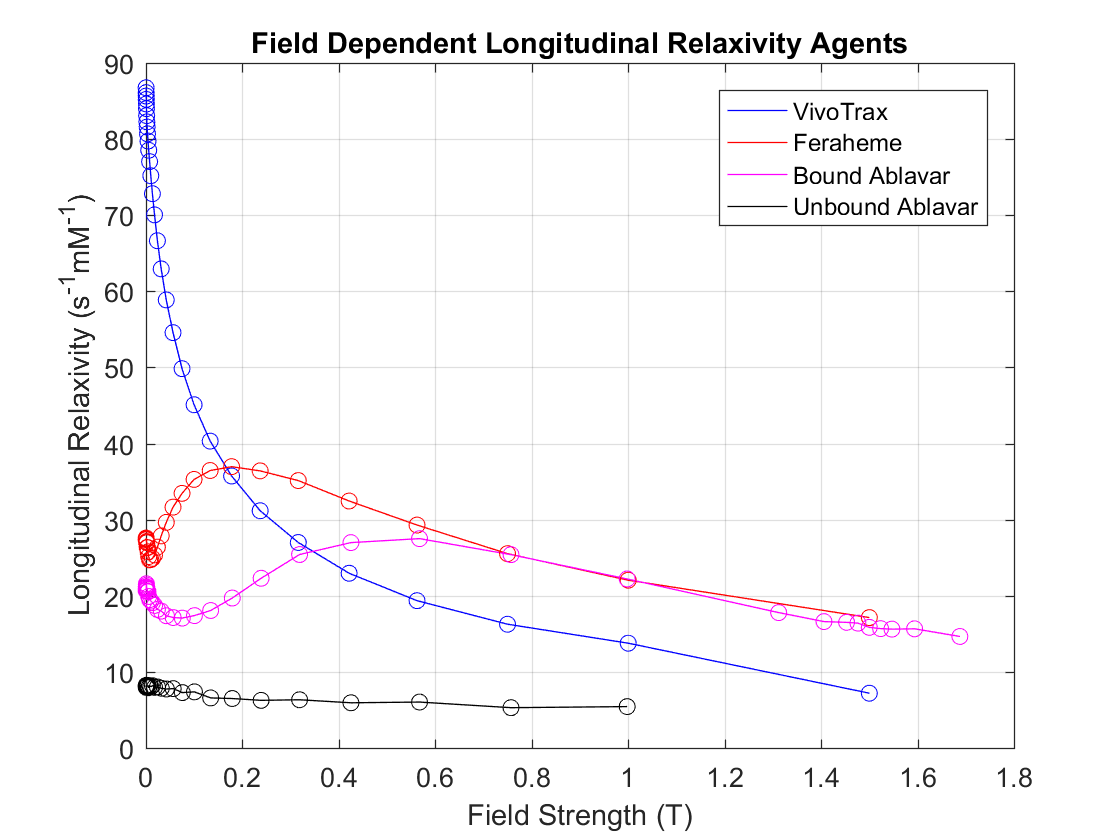
Delta relaxation enhanced magnetic resonance (dreMR) is a promising field-cycling based quantitative molecular imaging method for contrast-enhanced MRI and molecular imaging. DreMR uses a B0 insert magnet to shift the magnitude of the main magnetic field of an MRI as a pulse preparation phase of the pulse sequence. Using field-dependent longitudinal relaxivity (r1) contrast agents, images taken at different field strengths provided by the dreMR insert can be subtracted, resulting in signal proportional to the concentration of these agents. Furthermore, with the use of “activatable” MR probes —contrast agents which have strong r1 field dependence when bound, this image subtraction technique can create images based upon bound agent only.1 Many contrast agents such as VivoTrax and Feraheme, and activatable probes such as Ablavar experience higher field dependence at 0.5T than standard clinical field strengths (1.5T, 3T). This means that if imaging is done at a lower field strength, specifically at 0.5T, a dreMR insert can be developed with a high contrast resulting from a small field shift, decreasing the amount of current and number of windings required. To explore possible dreMR inserts for a new MR system at 0.5 T, a novel approach has been taken to improve upon previous designs by using the boundary element method (BEM)2-4 to correct for field inhomogeneity in the dreMR system, resulting in a dreMR coil with greatly improved homogeneity compared to previous designs (~5% for Alford et al and Harris et al).1,5 An active shield designed by the BEM can easily be added, using the methods outlined in previous work.5METHODS
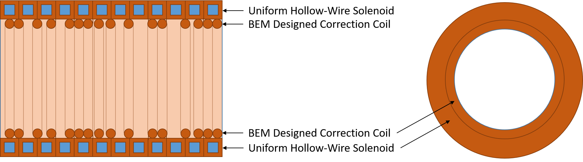
Our approach begins by choosing the number of radial and axial windings (NR, NZ) of the outer solenoid required to bring us close to the desired field shift (ΔB0) with the available amplifier which would be composed of square hollow wire of known width. A mesh of regular triangles is created in a meshing program to use as a surface on which current can flow to correct the homogeneity. This surface is located just inside the solenoid radially and is intended to be constructed from finer wire than the hollow, water cooled solenoid, and be cooled by its proximity. The wire pattern of the solenoid is used to calculate the field at random points (P) on a spherical surface with radius 75% that of the coil’s inner radius using Biot-Savart’s Law. Differences between the field at P and the field at the isocenter were then used as field targets for the BEM –previously used for designing gradient coils and their shims, to create a current density on the mesh that would negate these differences and thus homogenize the dreMR field. Given the cylindrical symmetry of the problem, the stream function calculated by the BEM on a regular mesh can be averaged to remove irregularities in the solution. As a preliminary study of the design space, the diameter of spherical volume (DSV) with field inhomogeneity below 1% was found for each coil design by changing the number of windings radially and axially, and by varying the inner radius (a1) for a picked coil winding. Designs were evaluated based on their ΔB0 and DSV<1%. This is only a first step and a more complete exploration of the design space will be carried out before construction.RESULTS
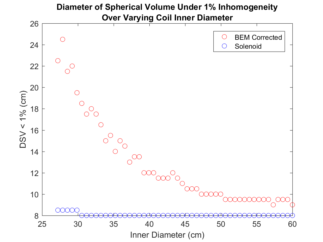
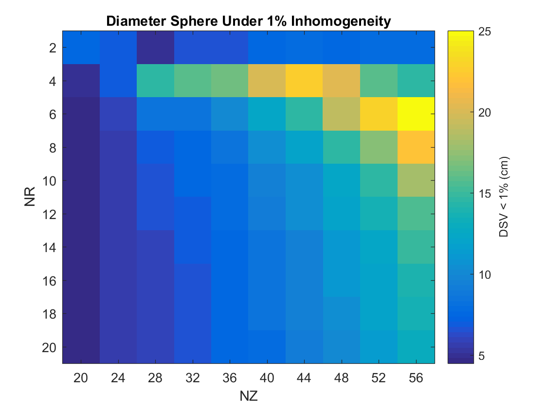
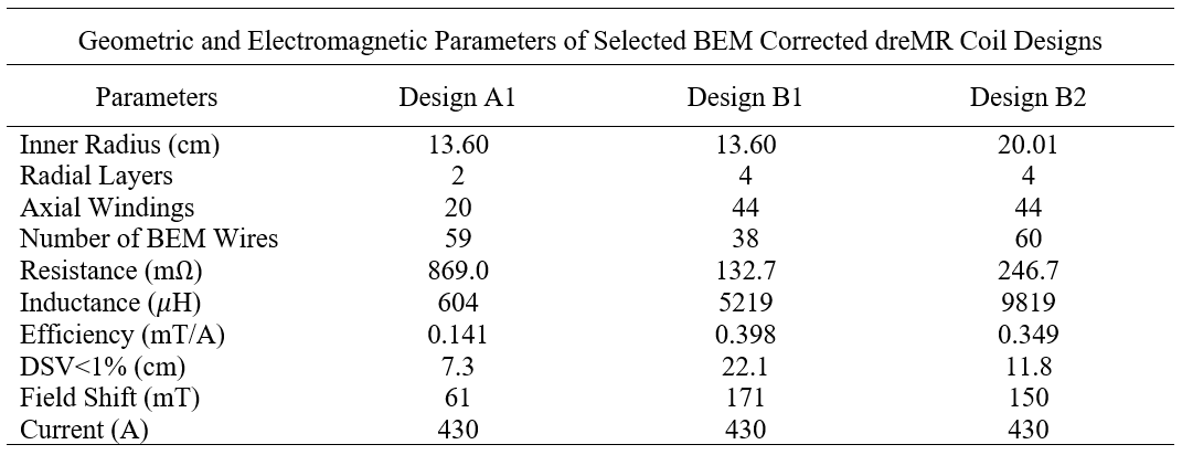
Figure 1 Shows a diagram of a BEM corrected dreMR coil. The DSV<1% for a coil with NR=4 and NZ=44 over varying radius is shown in Figure 2 and a grid search of DSV<1% for varying windings at a1=13.6cm is shown in Figure 3. VivoTrax, Feraheme, and Ablavar longitudinal relaxivity data for varying B0 can be found in Figure 4. Table 1 compares the properties of coils designed with BEM correction.DISCUSSION
It was found that as a1 was increased and axial length held constant, the DSV<1% and ΔB0 decreased. Therefore, coils designed with this method should have the minimum a1 feasible for the desired imaging region, though as seen in Table 1 larger coils are feasible. A grid search of solenoid windings showed that as the total number of windings (N) increased, ΔB0 and DSV<1% increased. While coils with many windings could be designed with strong ΔB0 and high homogeneity, the weight and space requirements of such coils become strong limiting factors and require a move away from the optimal Fabry parameter.6 Going forward the space available for a dreMR system and heating considerations will constrain designs, but it is important to note that the homogeneity in the imaging region of a field shifting coil can be greatly improved using the addition of a field correction layer. A full exploration of the parameter space for the design method will likely yield even more improvement.CONCLUSION
Here we have outlined a new method for the development of homogeneous field shifting dreMR insert coils, using the BEM to correct the field of a standard solenoid. It has been seen through simulation that such coils, if used in a 0.5T field strength MRI system, may produce significant signal from active MR probes and contrast agents for a small field shift, and thus greatly benefit from improved homogeneity.Acknowledgements
The authors would like to acknowledge financial support from NSERC, the Ontario Research Fund, and the Ontario Graduate Scholarship.References
1. Alford J, Rutt B, Scholl T, et al. Delta relaxation enhanced MR: Improving activation-specificity of molecular probes through R1dispersion imaging. Magnetic Resonance in Medicine. 2009;61(4):796–802.
2. Poole M, Bowtell R. Novel gradient coils designed using a boundary element method. Concepts in Magnetic Resonance Part B: Magnetic Resonance Engineering. 2007;31B(3):162–175.
3. Peeren G. Stream function approach for determining optimal surface currents. Journal of Computational Physics. 2003;191(1):305–321.
4. Harris, C. T. "Optimization of a boundary element approach to electromagnet design with application to a host of current problems in Magnetic Resonance Imaging" (2013). Electronic Thesis and Dissertation Repository. 1422. https://ir.lib.uwo.ca/etd/1422.
5. Harris C, Handler W, Araya Y, et al. Development and optimization of hardware for delta relaxation enhanced MRI. Magnetic Resonance in Medicine. 2013;72(4):1182–1190.
6. Montgomery DB. Solenoid Magnet Design: The Magnetic and Mechanical Aspects of Resistive and Superconducting Systems. New York: Wiley; 1969.
Figures