1256
A short-bore helium-off 7 T whole-body MRI superconducting magnet design1Institute of Electrical Engineering, Chinese Academy of Sciences, Beijing, China, 2Department of Radiotherapy Cancer Center, Guangdong Provincial People's Hospital & Guangdong Academy of Medical Science, Guangzhou, China, 3School of Biomedical Engineering, Southern Medical University, Guangzhou, China, 4School of Information Technology and Electrical Engineering, The University of Queensland, Brisbane, Australia
Synopsis
7T whole-body MRI system has received comprehensive praises from the worldwide users, but some patients feel clautrophobic when doing the scanning at the long tunnel. This work proposed a ultra-short design scheme for the 7 T MRI magnet, which is nearly a half of the presented commercial system. In addition, the magnet operates at helium-off enviroment, which saves the precious coolant liquid helium and is also conveinent to maintain.
Introduction
7 T magnetic resonance imaging system (MRI) has gone into clinical application and its superior imaging quality has received significant compliments 1, 2. However, the long tunnel of the bulk system (around 3 m) may be horrifying to some patients who are claustrophobic. In addition, conventional superconducting MRI magnet relies on liquid helium to maintain extremely low temperature for superconducting wire, but the situation is grim as the helium resource is less and less and the price increases rapidly. Therefore, the helium-off MRI system is being widely welcomed 3. This work presents a short-bore 7 T whole-body MRI superconducting magnet design with high-temperature superconducting (HTS) YBCO tape that operates without liquid-helium cooling.Method
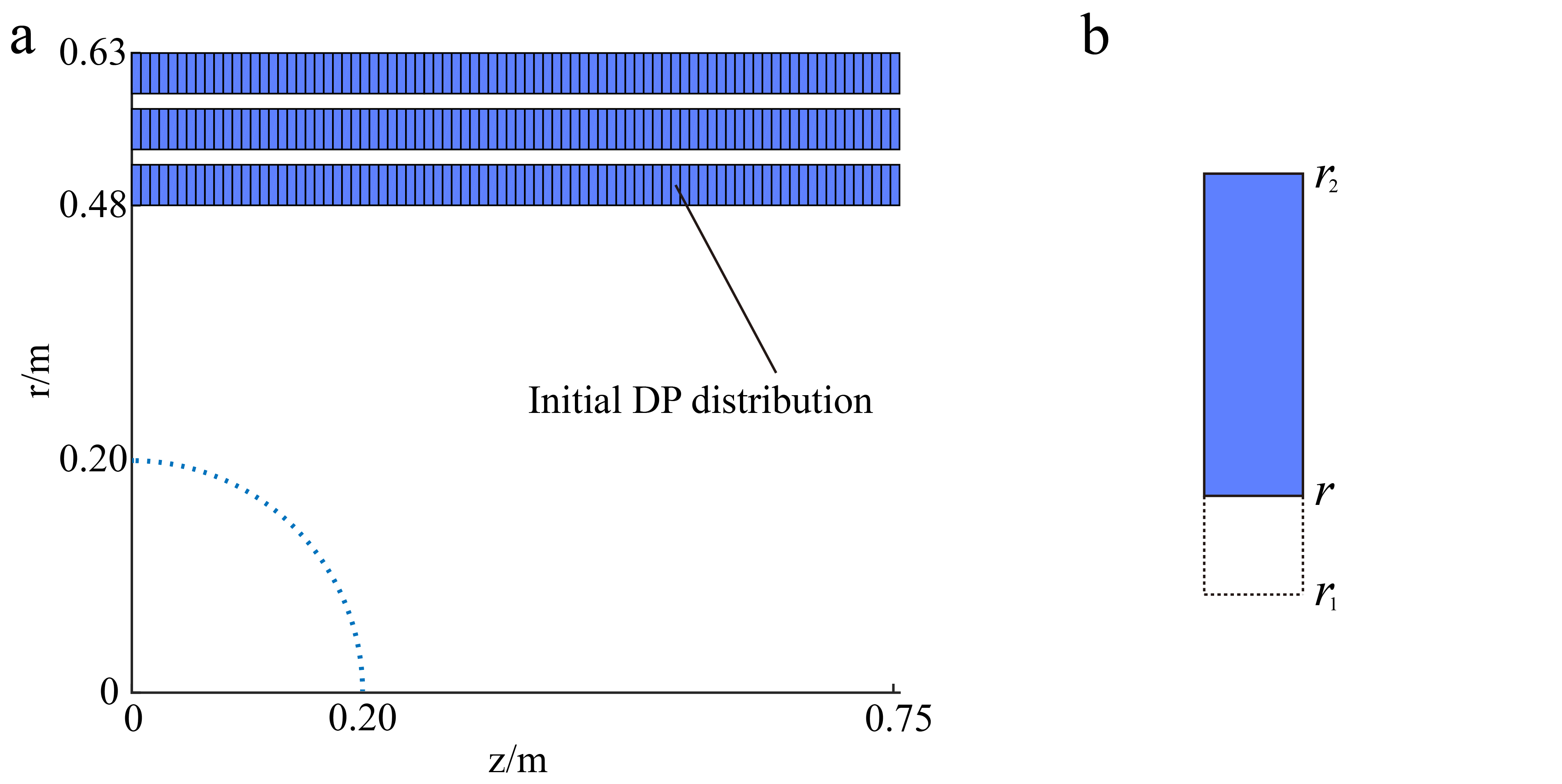
The magnet design adopted double-pancake (DP) coil as the basic element. In order to reduce the stress level and facilitate coil binding, a three-layer DP structure was used as the initial magnet configuration. Fig. 1(a) shows the DP layout, where there are totally 84×3 meshes and the width of each mesh corresponds to a DP thickness 9 mm. Due to symmetry, only a half of the magnet coils were considered in the magnetic field computing. The first step was to find the rough coil configuration that meets the magnetic field homogeneity requirement realized by a linear optimization 4. The initially optimized result often contains some DPs which have current densities that are not exactly equivalent to the designated input, so a second-step optimization is to use the notch DP structure to homogenize the magnetic field profile 5. That is, the notch DP will have an inner radius r between the inner radius r1 and outer radius r2 of the normal DP, as shown in Fig. 1(b).Results
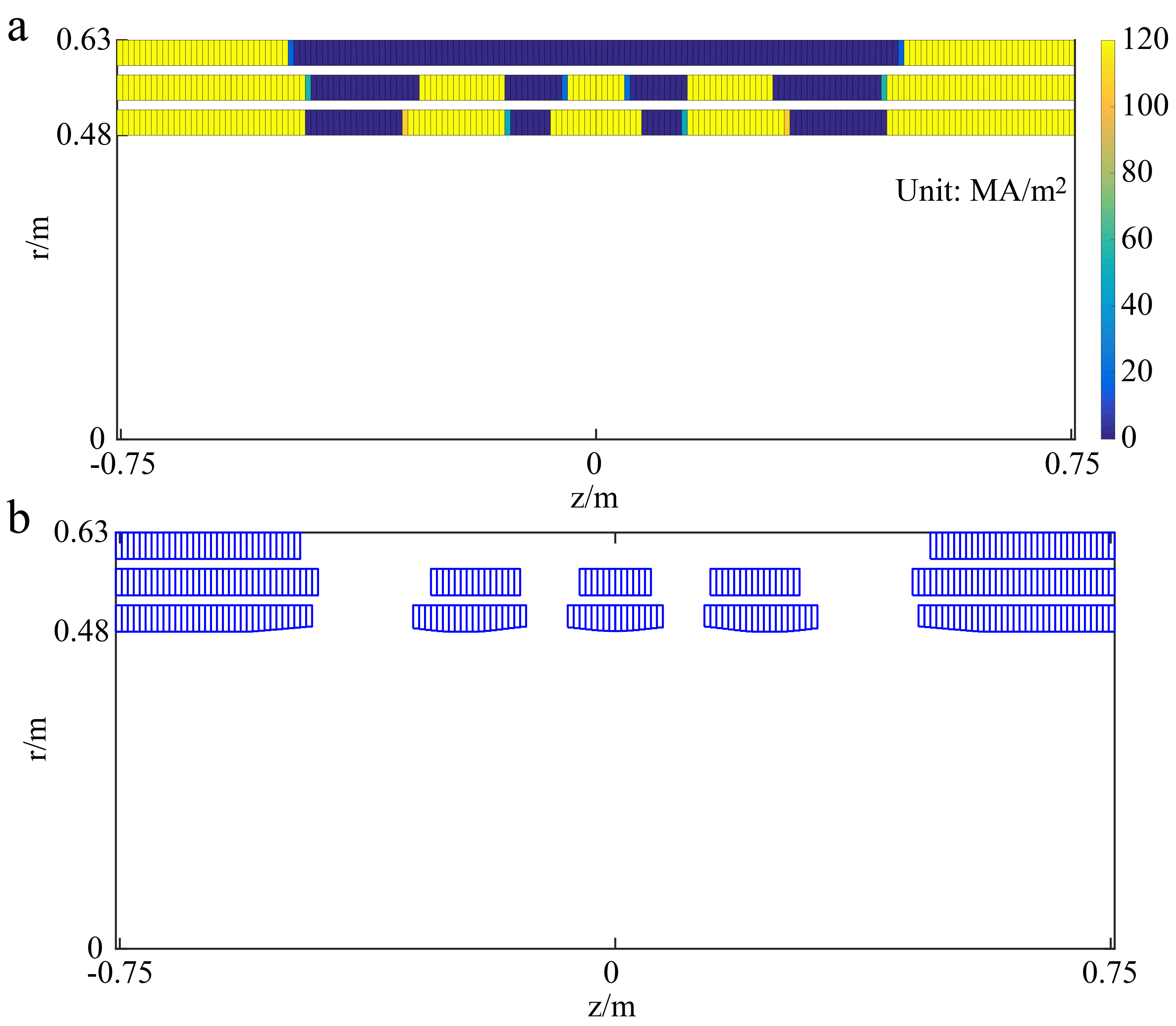
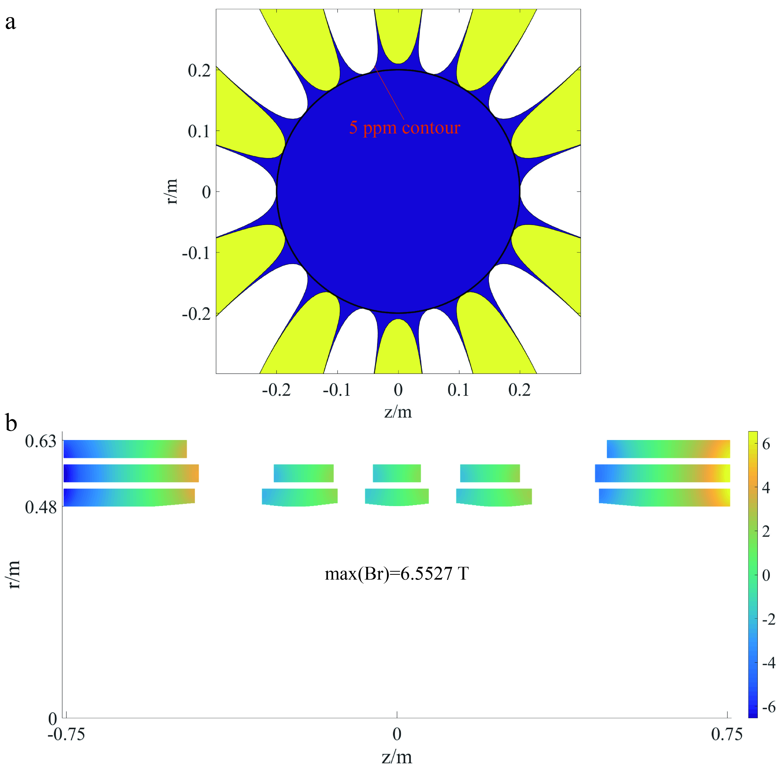
Fig. 2 shows the DP optimization results, where Fig. 2(a) is magnet configuration after the first-step optimization and Fig. 2(b) depicts the final DP pattern. From Fig. 2(a), it can be seen that there are 12 coils in the magnet structure with specific longitudinal positions. During the notch DP optimization, the DP dimensions in the second and third layered were kept fixed and the only DPs to be notched were in the first layer. This reduced the coil complexity and ensured that most DPs could be fabricated in an identical mold.Fig. 3 illustrates the magnetic field performance of the magnet design. The contours in Fig. 3(a) denote the 5-ppm magnetic field deviation over the target magnetic field and the circle indicates the imaging area. The perpendicular magnetic field distribution in the magnet coils were displayed in Fig. 3(b) and the maximum magnetic field intensity is 6.5527 T.
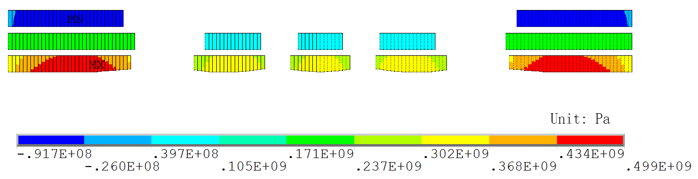
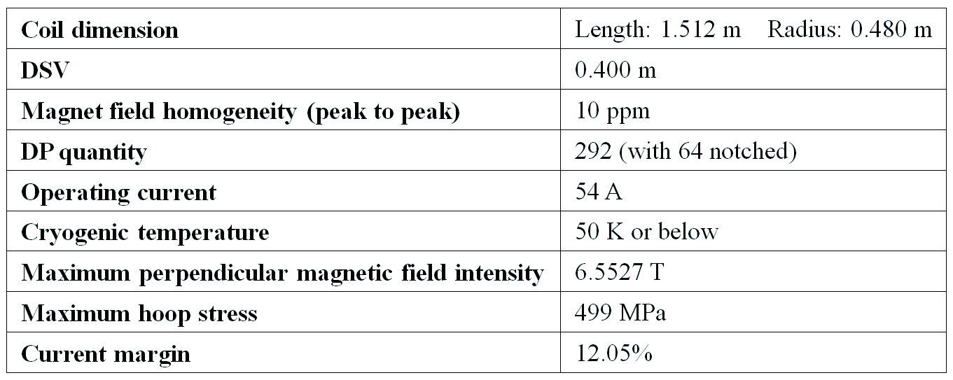
Fig. 4 presents the hoop stress distribution in the magnet coils. It can be seen that the maximum stress level occurs at the outmost magnet coils of the first layer with a value 499 MPa, which is tolerable for the YBCO tape and it can be reduced significantly with pre-stress and binding. The coil parameters of the 7T whole-body MRI superconducting magnet were listed in Table I.
Discussions
Due to limitation of a single YBCO tape length, superconducting joints have to be used in the DPs. The layer intervals between the coils were 15 mm, which contained planned DP skeleton, bobbin, binding and assembling gap. The magnet was designed at a cryogenic temperature 50 K, which is much higher than liquid helium boiling point, so a conduction-cooled method or solid nitrogen protection will be used to keep the superconductivity of magnet coils.Conclusion
This work presented a design of the short-bore helium-off whole-body MRI superconducting magnet. The magnet coil had a length only around 1.5 m. A notch DP method was adopted for the magnetic field homogeneity optimization that resulted in 64 notches in total 292 DPs. The magnet was planned to operate at a temperature 50 K where it had a current margin 12.05% and it could be increased when the operating temperature was lower. The magnet coils had a maximum hoop stress 499 MPa, which is under the safe condition of YBCO tape.Acknowledgements
This work is funded by CAS Pioneer Hundred Talents Program (Grant No. Y8402A1C31), Beijing Science and Technology Plan (Grant No. Z181100003818020), International Partnership Program of Chinese Academy of Sciences (Grant No. 182111KYB20170067, No. 182111KYSB20170039).References
1. B. P. Thomas, E. B. Welch, B. D. Niederhauser, W. O. W. Jr, A. W. Anderson, J. C. Gore, et al., "High-resolution 7T MRI of the human hippocampus in vivo," Journal of Magnetic Resonance Imaging, vol. 28, pp. 1266-1272, 2008.
2. S. J. Van Veluw, J. J. M. Zwanenburg, J. Engelen-Lee, W. G. M. Spliet, J. Hendrikse, P. R. Luijten, et al., "In vivo detection of cerebral cortical microinfarcts with high-resolution 7T MRI," Journal of Cerebral Blood Flow & Metabolism, vol. 33, pp. 322-329, 2013.
3. Iwasa and Yukikazu, "Towards liquid-helium-free, persistent-mode MgB2 MRI magnets: FBML experience," Superconductor Science & Technology, vol. 30, p. 053001, 2017.
4. Z. Ni, Q. Wang, F. Liu, and L. Yan, "A homogeneous superconducting magnet design using a hybrid optimization algorithm," Measurement Science and Technology, vol. 24, p. 125402, 2013.
5. J. Bascunan, Seungyong Hahn, Youngjae Kim, Jungbin Song, and Y. Iwasa, "90-mm/18.8-T All-HTS Insert Magnet for 1.3 GHz LTS/HTS NMR Application: Magnet Design and Double-Pancake Coil Fabrication," IEEE Transactions on Applied Superconductivity, vol. 24, pp. 1-4, 2014.
Figures