1252
Design of a Permanent Magnet for MRI of the Ankle on the International Space Station1Department of Oncology, University of Alberta, Edmonton, AB, Canada, 2Department of Psychology and Division of Biomedical Engineering, University of Saskatchewan, Saskatoon, SK, Canada, 3LT Imaging, Toronto, ON, Canada, 4AGH University of Science and Technology, Krakow, Poland, 5MRI-Tech Sp. z o.o, Krakow, Poland, 6Institute of Nuclear Physics, Polish Academy of Sciences, Krakow, Poland
Synopsis
MRI is desired for monitoring bone and muscle deterioration in astronauts during long-term spaceflights and on the International Space Station (ISS). However, the magnet is generally too heavy to be transported to the ISS. Therefore, we designed a light (~10kg) magnet that allows transmit array spatial encoding (TRASE) MRI of the ankle on the ISS. The magnet is based on a sparse Halbach geometry with magnetic block-pairs. The positions of the block-pairs were optimized using a genetic algorithm. We intend to manufacture the magnet and test the entire MRI system on a Falcon 20 jet.
Introduction
Bone and muscle deterioration is a major concern for humans in a zero-gravity environment, such as long missions on the International Space Station (ISS). Astronauts lose 1-2% of their bone mineral density per month in zero-gravity and up to 50% muscle loss on long missions1, significantly increasing risk of fractures and muscle pain when returning to Earth. While most astronauts restore bone loss to normal levels within approximately 3 years some do not recover1. Therefore, countermeasures during flights are the current focus of research1. One of the most useful monitoring methods for bone and muscle loss is MRI, but current MRI systems are too heavy and cumbersome. The requirements for an MRI magnet suitable for the ISS2 are listed in Table 1. The major obstacle is the weight of the MRI magnet.As standard magnets and MRI methods do not meet these requirements, we propose to take advantage of the lesser requirement for homogeneity of the magnetic field needed for the transmit array spatial encoding (TRASE) technique, that recently allowed collection of high quality TRASE images3-6.
Our aim was to design a light magnet, based on the sparse Halbach geometry7,8, which produces the field allowing selective excitation in the center of the magnet (perpendicular to z) and 2D TRASE in the x,y plane. Bloch equation simulations showed that 100μs non-selective RF pulses (90° and 180°) will refocus spin echoes over a 3kHz bandwidth (corresponding to the selected volume). Therefore, we designed a magnet allowing selective excitation of the volume within the 3kHz, with rapid field drop-off outside of the frequency band.
Methods
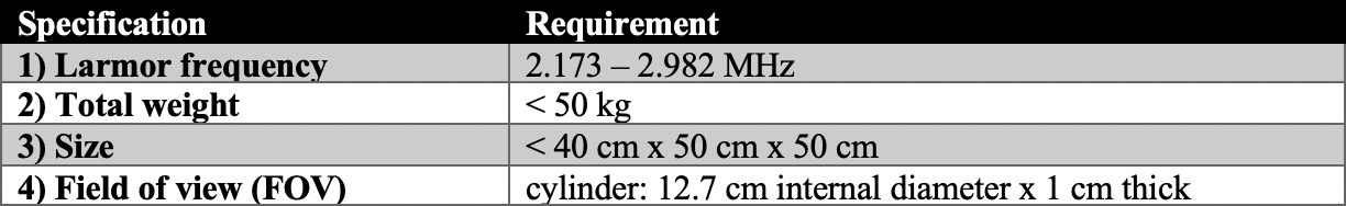
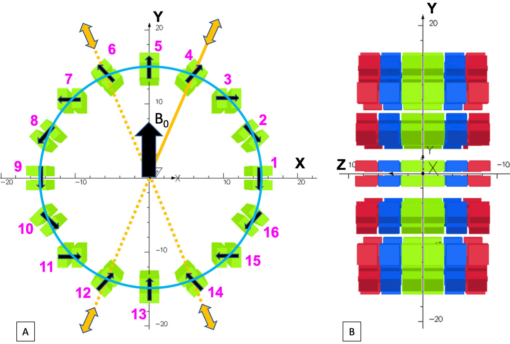
As the initial configuration for the optimization, we used six identical rings (Fig 1A,B) of 29.2cm diameter placed 3mm apart. Each ring was made of sixteen NdFeB block-pairs (2.54cm x 2.54cm x 1.27cm each). This initial configuration generates a magnetic field of ~60 mT at the geometric center. The block-pairs enable safe mounting to a 3D printed frame due to their self-attraction9. The magnetization direction rotates between each neighbouring pair by 22.5° generating the vertical magnetic field B0 (Fig 1A).The optimization process using the genetic algorithm (GA) minimizes the difference between the maximum and minimum field (fitness function) within a 12.7cm diameter and 1 cm thick cylindrical FOV by sampling the radial positions of the block-pairs in each ring independently (-2 to +3cm from the perimeter) providing sufficient space for RF coils and the ankle. Due to the symmetry of the block-pairs (dotted line in Fig 1A), only five positions of the block-pairs need to be optimized within each ring. For example, the movement of the block-pair 4 implies the same movement of the blocks 6, 12 and 14 (Fig 1A).
Magnetostatics simulation software (OperaFEA, Cobham, UK) using finite element analysis and a communication server with the GA imbedded in MATLAB (The MathWorks, US) were used for the field calculations and optimization respectively. Most software packages do not take into account the actual BH curve of magnetic blocks yielding errors in the magnetic field distribution produced by a manufactured magnet. Therefore, in our simulations, we used the actual BH curve provided by a manufacturer.
Results
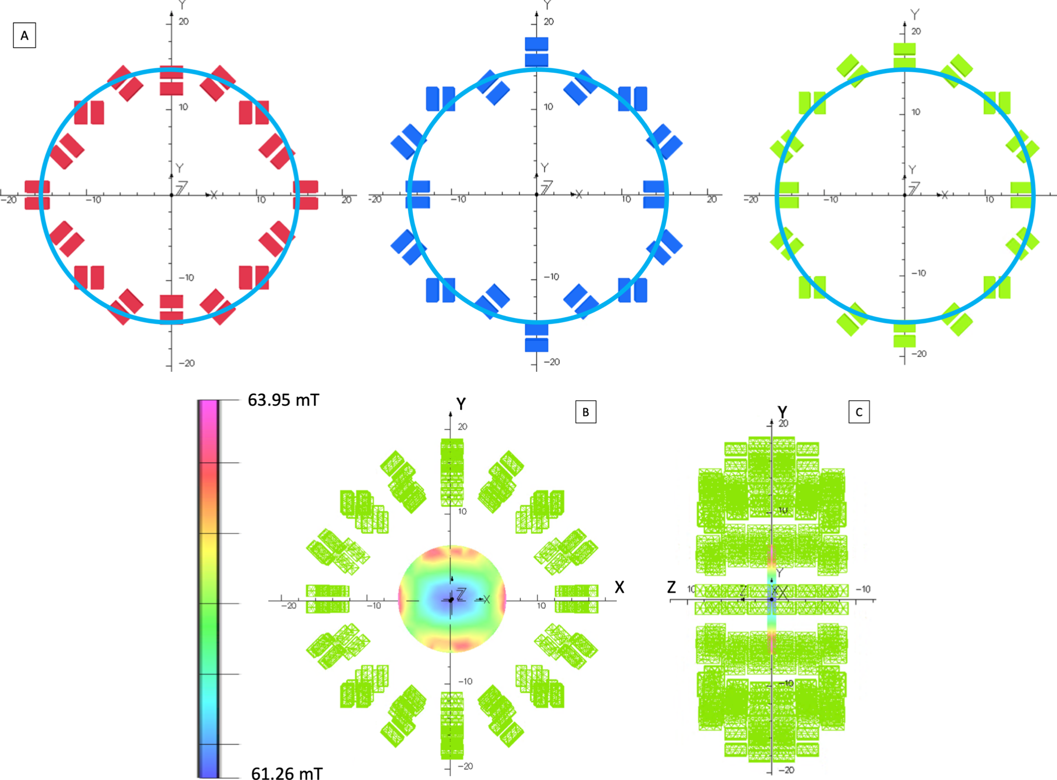
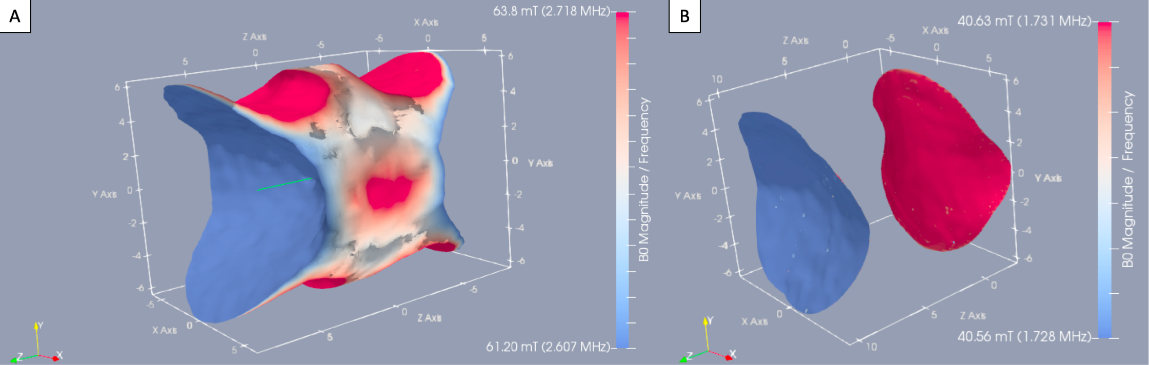
A significant improvement (7.5 times) in homogeneity from the initial configuration within the FOV was achieved using the described optimization method. The values of the optimized positions of the block-pairs of the green, blue and red rings (Fig 1B) relative to their initial non-optimized positions were found to be: [-1.36,0.92,0.44,2.04,2.31], [-0.96,-1.70,-0.86,-1.67,2.93] and [2.01,2.89,-0.28,0.95,-0.29] cm respectively (Fig 2A). Figures 2B and 2C show the optimized magnet. The cone-like iso-frequency surfaces (corresponding to the same Larmor frequency) are shown in Figs 3 and 4 for selected frequencies and bandwidths (BW). These shapes may be utilized to excite specific volumes using variable BW and frequencies by the TRASE technique.Discussion
The proposed design may be suitable for ankle MR imaging on the ISS using TRASE. The total weight of the magnet is significantly less than the maximum 50kg allowed for ISS. The entire MRI system is expected to weigh ~30kg. The choice of the frequencies and BWs provides opportunities for the selection of desired excitation volume. Furthermore, it may be possible to excite more than one volume of interest simultaneously by utilizing the frequency of the RF field in each volume. Additionally, the cone-like field shape may be modified by applying an axial gradient, that may also provide opportunity for multi-slice 2D TRASE imaging using selective pulses.In future designs, magnetic field homogeneity may be improved further by optimizing magnetization directions10. Due to construction errors, homogeneity is expected to be lower than calculated. To minimize these errors, each block-pair could be movable within a frame allowing shimming. Additional steel blocks and/or small magnet blocks could be secured to the frame for fine field shimming.
Conclusion
Design of a magnet for TRASE MRI on the ISS is possible. Optimization using the GA for the radial positions of the magnetic blocks improves the homogeneity of a sparse Halbach magnet to meet the criteria of the ISS MRI system.Acknowledgements
This study was funded by the Natural Sciences and Engineering Research Council of Canada (NSERC), NSERC Discovery Grant, Grant/Award number: RGPIN-03992.References
[1] Williams, D., Kuipers, A., Mukai, C., and Thirsk,R. (2009). Acclimation during space flight: effects on human physiology. Canadian Medical Association Journal. 180(13) 1317-1323.
[2] Sarty, G.E., Scott, A., Turek, K., Liszkowski, P., Sharp, J.C., and Tomanek B. (2014). A wrist MRI for the International Space Station. 65th International Astronautical Congress, Toronto, Canada. Published by the IAF.
[3] Sharp, J.C., King, S.B., Deng, Q., Volotovskyy, V., and Tomanek B. (2013). High-resolution MRI encoding using radiofrequency phase gradients. NMR in Biomedicine. 26: 1602-1607.
[4] Sun, H., AlZubaidi, A., Purchase, A., and Sharp, J.C. (2019). A Geometrically Decoupled, Twisted Solenoid Single-Axis Gradient Coil Set for TRASE. Magnetic Resonance in Medicine. DOI:10.1002/mrm.28003
[5] Purchase, A.R., Palasz, T., Sun, H., Sharp J.C., and Tomanek B. (2019). A high duty-cycle, multi-channel, power amplifier for high-resolution radiofrequency encoded magnetic resonance imaging. Magn Reson Mater Phy, 32(6): 679-692.
[6] Bohidar, P., Sun, H., Sarty, G.E., and Sharp, J.C. (2019). TRASE 1D sequence performance in imperfect B1 fields. Journal of Magnetic Resonance. 305: 77-88.
[7] Cooley, C.Z., Haskell M.W., Cauley, S.F., Sappo, C., Lapierre, C.D., Ha, C.G., Stockmann, J.P., Wald, L.L. (2018). Design of Sparse Halbach Magnet Arrays for Portable MRI Using a Genetic Algorithm. IEEE Transaction on Magnetics. 54 (1): 510012.
[8] Sarty, G.E. and Vidarsson, L. (2018). Magnetic resonance imaging with RF on curved natural slices. Magnetic Resonance Imaging 46: 47-55.
[9] Vidarsson, L. (2018). US Patent. US 10018694B2.
[10] Kuster, G. (2010). Computation of NdFeB-Halbach Cylinders With Circular and Elliptical Cross Sections in Three Dimensions. IEEE Transactions on Magnetics. 46: 3601-3607.
Figures