1250
A Point-of-Care MRI Scanner for Human Brain Imaging1Athinoula A Martinos Center for Biomedical Imaging, Dept. of Radiology, Massachusetts General Hospital, Charlestown, MA, United States, 2Harvard Medical School, Boston, MA, United States, 3Dept. of Electrical Engineering, Massachusetts Institute of Technology, Cambridge, MA, United States, 4Harvard-MIT Division of Health Sciences and Technology, Cambridge, MA, United States
Synopsis
Access to MRI scanners is limited by cost, size, and siting requirements. Specialized low-cost, compact, portable systems could greatly increase accessibility worldwide and enable point-of-care MRI. We present a portable MRI scanner for human brain imaging based on a compact 122kg Halbach cylinder with a built-in readout field. Designing for a built-in encoding field reduces the size of the magnet, the overall system power-consumption, cooling requirements, and acoustic noise. The generalized reconstruction method accounts for non-linearities in the gradient fields. T1 and T2-weighted in vivo images are presented with a resolution of 2x2x7mm.
Introduction
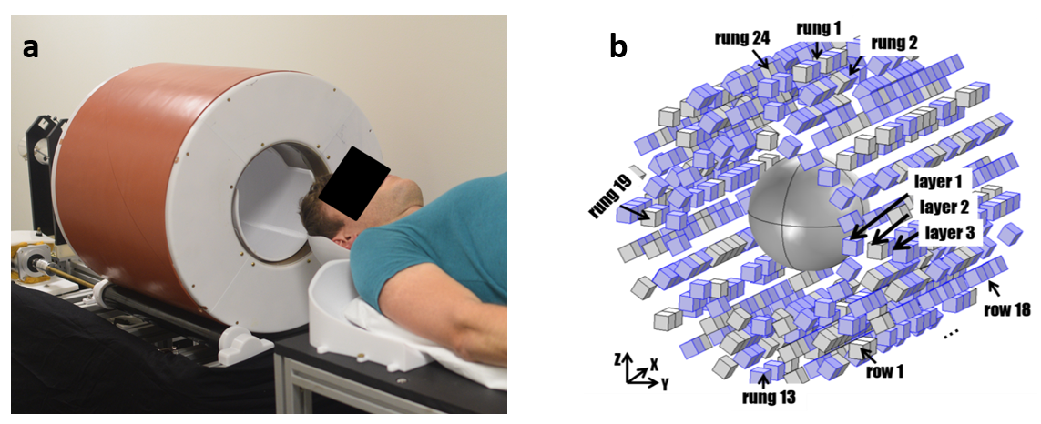
Access to MRI is limited by cost, size, and siting requirements. Specialized portable systems could increase accessibility and enable point-of-care (POC) MRI. We developed a head-only, portable, low-field MRI scanner based on a compact permanent magnet array (Figure 1a) weighing 122kg. The scanner operates from a standard wall outlet, requires no cooling, and all components are mounted on a cart that could be transported to a patient’s room. Building off of previously described design stages1–9, here we present the overall approach and in vivo brain imaging validation.Methods
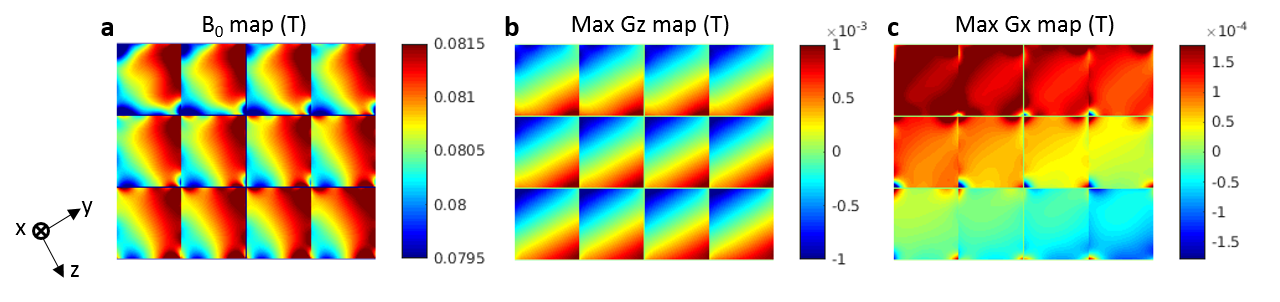
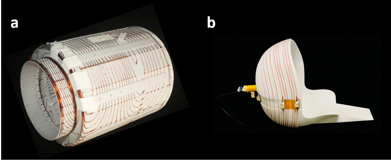
The prototype scanner shown in Figure 1 uses a sparse array of NdFeB magnets in a Halbach cylinder configuration. Instead of maximizing homogeneity, the design was optimized to tailor the field variation into a favorable gradient field for read-out encoding7. This was initially done with a genetic algorithm for the 1” cube NdFeB arrangement7, followed by a shimming stage with smaller NdFeB elements9. Figure 2a shows the magnetic field-maps, including the built-in (non-linear) readout field. The average B0 field is 80mT and the Y gradient is ~7.6mT/m. The built-in gradient limits the sequences to spin-echoes (RARE), but allows standard T2, IR-prepped T2, T1, proton density (PD) and diffusion contrasts. The built-in gradient design reduces the magnet cost and weight and the system’s acoustic noise and power/cooling needs (associated with a readout gradient coil in an inhomogeneous field).Generalized projection imaging was previously presented by rotating the magnet4,5. However, here we present imaging using efficient gradient coils for phase encoding in X and Z. Unlike the readout, phase encoding gradients in a spin-echo sequence need not dominate the B0 inhomogeneity since this is refocused in the spin-echo. The compact gradient coils were designed on the surface of a cylinder that fits tightly in the magnet bore (Fig. 3a). A BEM stream function method was used to optimize the surface current density for linearity in the ROI8. The efficiencies of the gradient coils are Gxeff = 0.6mT/m/A and Gzeff = 0.8mT/m/A. Less than 10A is used to drive the coils at a low-duty cycle (3-5%), allowing for passive air-cooling.
To correct for imperfections in the compact magnet and gradient coil field patterns, we apply a model-based generalized image reconstruction technique that corrects distortion, a popular method used with non-linear encoding fields10–12,4. The encoding model uses the measured field-maps of the built-in readout gradient (Fig. 2a) and the gradient coils (Fig. 2b,c), and models the encoding process in our 3D RARE sequences.
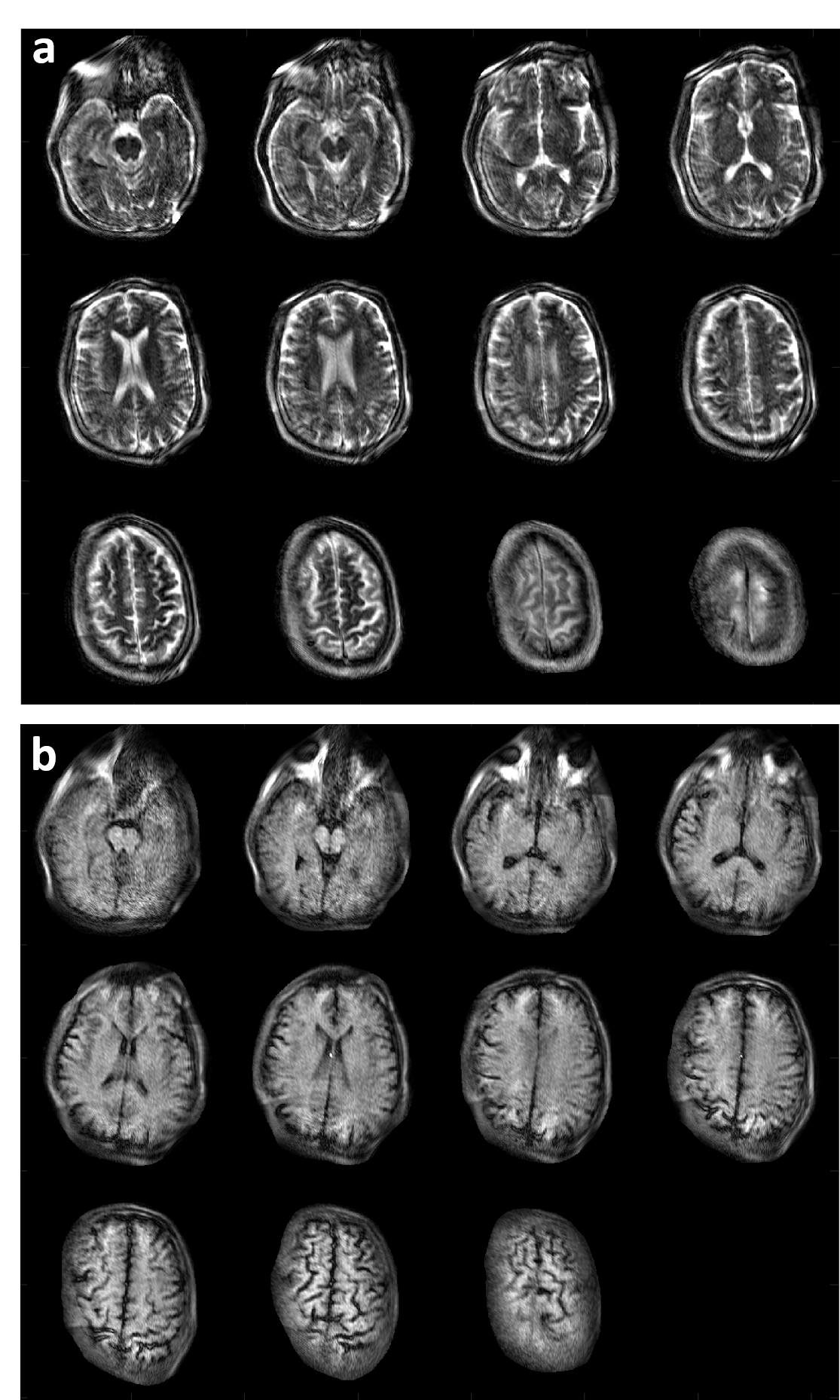
The sequences use a RARE spin-echo train with frequency-swept WURST RF pulses13. For T2-weighting, the X-dimension (partition) phase encoding is performed along the echo train with a linear k-space trajectory. The Z-dimension gradient phase encoding is incremented linearly shot to shot. In vivo T2-weighted results shown in Figure 4 use a TR/TEeff of 3s/167ms, 23 PEs in X, and 97 PEs in Z, yielding image resolution ~2x2x7mm. The proton density sequence uses a “center-out” k-space ordering down the echo-train, yielding a TEeff = 14ms. T1 sequence is similar but includes an IR prep; TR/TEeff/TI = 1.8s/14ms/400ms for in vivo results in Fig. 4. Peak currents of 9A and 4.5A were used to the drive the Z and X gradient respectively.
A spiral helmet coil5 was used for Tx/RX with an asymmetric 12 turn distribution to improve B1 homogeneity and BW = 70 KHz (Fig. 3b). A 50hm, 37db gain pre-amp (MITEQ model AU-1583) and second stage 24db gain amplifier (Minicircuits ZFL-500LN+) were used for the receiver. Additional hardware includes: a Tecmag Bluestone console, AE Techron 7224 gradient amplifiers, a 2kW-rated RFPA (Tomco BT02000-AlphaS-3MHz), and patient table constructed from aluminum strut.
Results
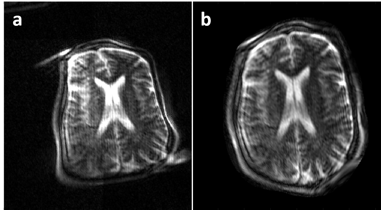
Preliminary images from healthy subjects acquired in a shielded environment are shown in Figure 4. The images have 2mm in-plane resolution and 7mm thick partitions. The T2 images were acquired in 19:24 minutes with 4 averages to improve SNR. The T1-weighted images were acquired in 11:46 minute with 2 averages. Figure 5 shows a reconstructed image assuming all linear encoding fields and the same data using the generalized model reconstruction.Discussion
Although some distortion is visible in all the images, Fig. 5 demonstrates the importance of the model-based reconstruction using measured encoding fields. These first images were acquired in a shielded room. Work is ongoing in suppressing RF interference through the combination of passive shielding around the magnet and active suppression in post-processing using external coils or electrodes. Work is also ongoing to replace high-cost equipment (console, RF amplifier and gradient amplifiers), with specialized low-cost options14–16.Conclusion
We present our portable MRI scanner for POC operation with in vivo brain imaging validation. Such a system could extend the reach of MRI into unconventional locations, such as ERs, ICUs, neonatal ICUs, and rural clinics. Our in vivo results demonstrate an image quality that is sufficient for monitoring and diagnosing many pathologies. Future work includes imaging studies with neurology patients at MGH.Acknowledgements
We would like to thank Monika Śliwiak for her
contributions and Matt Rosen and Neha Koonjoo for assistance with the spiral
head coil. Funding from NIH NIBIB R01EB018976 and
5T32EB1680.
References
1. Zimmerman, C., Blau, J., Rosen, M. S. & Wald, L. L. Design and construction of a Halbach array magnet for portable brain MRI. Proc. 20th Annu. Meet. ISMRM Melb. Aust. 2012 2575 (2012).
2. Cooley, C. Z., Stockmann, J. P., Armstrong, B. D., Rosen, M. S. & Wald, L. L. A lightweight, portable MRI brain scanner based on a rotating Halbach magnet. Proc. 21st Annu. Meet. ISMRM Salt Lake City Utah USA 2013 137 (2013).
3. Cooley, C. Z. et al. Spatial resolution in rotating Spatial Encoding Magnetic field MRI (rSEM-MRI). Proc. 22nd Annu. Meet. ISMRM Milan 2014 0033 (2014).
4. Cooley, C. Z. et al. Two-dimensional imaging in a lightweight portable MRI scanner without gradient coils. Magn. Reson. Med. 73, 872–883 (2015).
5. LaPierre, C., Sarracanie, M., Waddington, D. E. J. & Rosen, M. S. A single channel spiral volume coil for in vivo imaging of the whole human brain at 6.5 mT. Proc. 23rd Annu. Meet. ISMRM Tor. 2015 1793 (2015).
6. Cooley, C. Z. et al. Improved Uniformity of the Spatial PSF for Portable MRI Using an Optimized Rotating Magnet. Proc. 25th Annu. Meet. ISMRM Honol. 2017 1049 (2017).
7. Cooley, C. Z. et al. Design of Sparse Halbach Magnet Arrays for Portable MRI Using a Genetic Algorithm. IEEE Trans. Magn. 54, 1–12 (2018).
8. McDaniel, P., Cooley, C. Z., Stockmann, J. P. & Wald, L. L. 3D imaging with a portable MRI scanner using an optimized rotating magnet and gradient coil. Proc. 26th Annu. Meet. ISMRM Paris 2018 0029 (2018).
9. McDaniel, P., Cooley, C. Z., Stockmann, J. P. & Wald, L. L. A target-field shimming approach for improving the encoding performance of a lightweight Halbach magnet for portable brain MRI. Proc. 27th Annu. Meet. ISMRM Montr. 2019 0215 (2019).
10. Lin, F.-H. et al. Reconstruction of MRI data encoded by multiple nonbijective curvilinear magnetic fields. Magn. Reson. Med. 68, 1145–1156 (2012).
11. Schultz, G. et al. Reconstruction of MRI data encoded with arbitrarily shaped, curvilinear, nonbijective magnetic fields. Magn Reson Med 64, 1390–1403 (2010).
12. Stockmann, J. P., Ciris, P. A., Galiana, G., Tam, L. & Constable, R. T. O-space imaging: Highly efficient parallel imaging using second-order nonlinear fields as encoding gradients with no phase encoding. Magn Reson Med 64, 447–456 (2010).
13. Casabianca, L. B., Mohr, D., Mandal, S., Song, Y.-Q. & Frydman, L. Chirped CPMG for well-logging NMR applications. J. Magn. Reson. 242, 197–202 (2014).
14. Anand, S., Stockmann, J. P., Wald, L. L. & Witzel, T. A low-cost (<$500 USD) FPGA-based console capable of real-time control. Proc. Jt. Annu. Meet. ISMRM-ESMRM 2018 Paris 0948 (2018).
15. Arango, N., Stockmann, J. P., Witzel, T., Wald, L. L. & White, J. Open-Source, Low-Cost, Flexible, Current Feedback-Controlled Driver Circuit for Local B0 Shim Coils and Other Applications. Proc. Annu. Meet. ISMRM 2016 Singap. 1157 (2016).
16. Blücher, C. et al. COSI Transmit: Open Source Soft- and Hardware Transmission System for traditional and rotating MR. Proc. 25th Annu. Meet. ISMRM Honol. 2017 184 (2017).
Figures