1173
A multi-element transceive array for cervical spinal cord imaging at 7T1C.J. Gorter Center for High Field MRI, Department of Radiology, Leiden University Medical Center, Leiden, Netherlands, 2Vanderbilt University Institute of Imaging Science, Nashville, TN, United States, 3Department of Radiology and Radiological Sciences, Vanderbilt University Medical Center, Nashville, TN, United States, 4Department of Biomedical Engineering, Vanderbilt University, Nashville, TN, United States
Synopsis
Spinal cord
imaging at 7T MRI is challenging and limited by the need for dedicated RF coils.
In this study, we present a flexible coil design for cervical spinal cord
imaging at 7T. B1+ inhomogeneities were addressed by
using multichannel array and phased-based RF shimming. Dorsal and ventral nerve
roots, denticulate ligaments, and blood vessels were visible on axial
T2*-weighted images. Cross-sectional area measurements from C3-C4 cervical
levels were consistent with literature values.
Introduction
Despite the higher signal-to-noise ratio intrinsic to higher field MRI scanners, spinal cord studies at 7T are still limited due to challenges associated with imaging this small region1,2. One of the major challenges is the need for a dedicated spinal cord coil for 7T1. A multi-element transmit array is necessary to correct for intrinsic B1+ field inhomogeneities3-7 and this array should conform to subjects with different neck sizes, which in turn requires flexible coil elements. The coupling between individual elements of the array must be minimized, which is challenging when they are placed close together, and this coupling should be as subject-independent as possible. In this study, we show spinal cord images obtained with a highly decoupled five-element transmit array.Methods
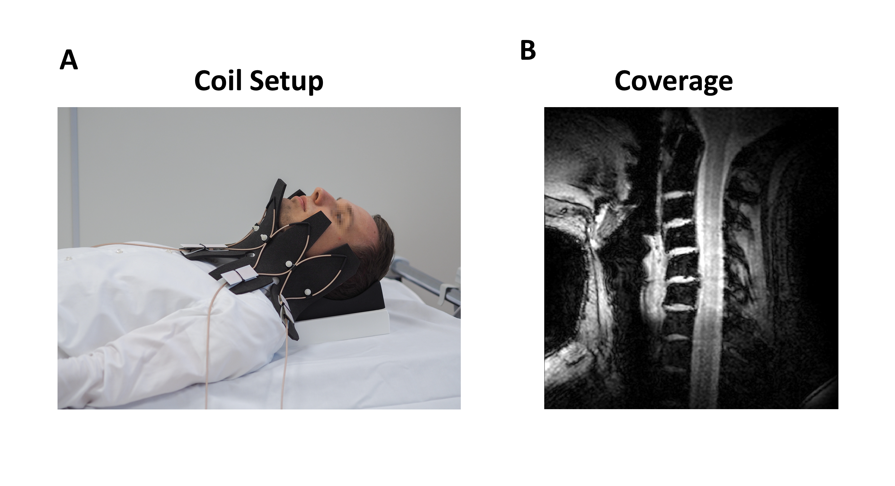
Coil Design and characterizationThe transceiver array was constructed from five individual elongated shielded-coaxial-cable coils8, each with a minor axis of 60 mm and a major axis of 160 mm, attached to a 10 mm thick layer of foam. S-parameters of the coil were measured in vivo on one of the healthy volunteers.
Data Acquisition and Analysis
Four healthy volunteers (one male, three female, age: 34 ± 14 years) with different neck sizes were scanned on a 7T Philips Achieva MRI scanner (Philips Healthcare, Best, the Netherlands) with parallel-transmit (Multix system) capability.
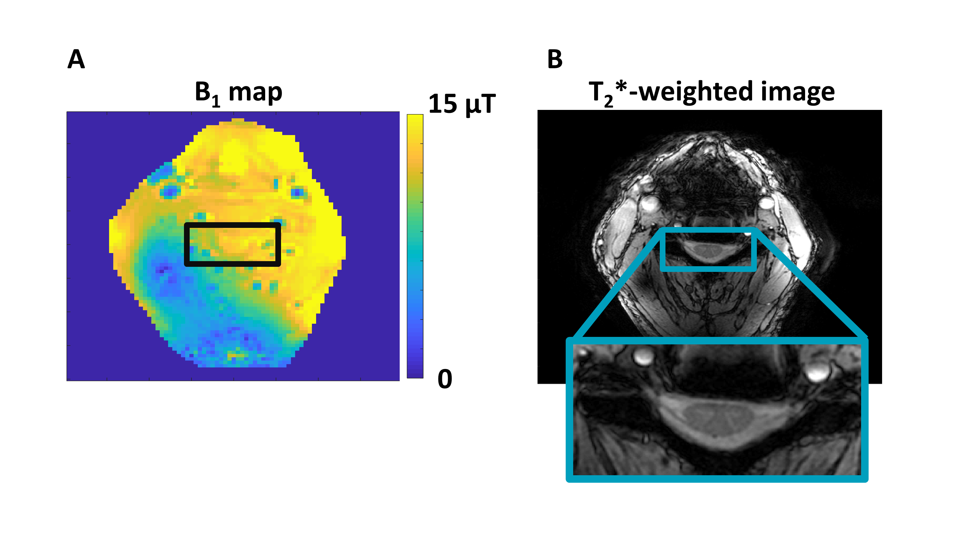
B1+ maps were obtained using the dual refocusing echo acquisition mode (DREAM) sequence9. B1+ maps were subsequently used to perform phase‐based B1 shimming. A linear optimization algorithm written in MATLAB® (Mathworks, Natick, MA, USA) was used to obtain the maximum B1+ in the spinal cord region of each volunteer. Equal magnitude excitation was used on all channels.
Axial T2*-weighted images were obtained from the cervical SC using multi-slice multi-echo gradient echo (mFFE) sequence. The scan parameters for a standard resolution scan were the following: FOV (AP × RL × FH) : 170 × 170 × 19.5 mm3, acquired voxel size (AP × RL × FH): 0.6 × 0.6 × 3.0 mm3, reconstructed voxel size: 0.27 × 0.27 × 3 mm3 , flip angle: 25°, TR/TE/ΔTE: 350 / 9 / 3.2 ms, 4 averages, scan time = 6 min 37 sec. Additionally, a high resolution scan was acquired from one of the volunteers with the following parameters: FOV (AP × RL × FH): 150 × 150 × 20 mm3, acquired voxel size (AP × RL × FH): 0.4 × 0.4 × 4.0 mm3, reconstructed voxel size: 0.29 × 0.29 × 4 mm3 , flip angle: 25°, TR/TE : 315 /14 ms, 3 averages, scan time: 5 min 56 sec.
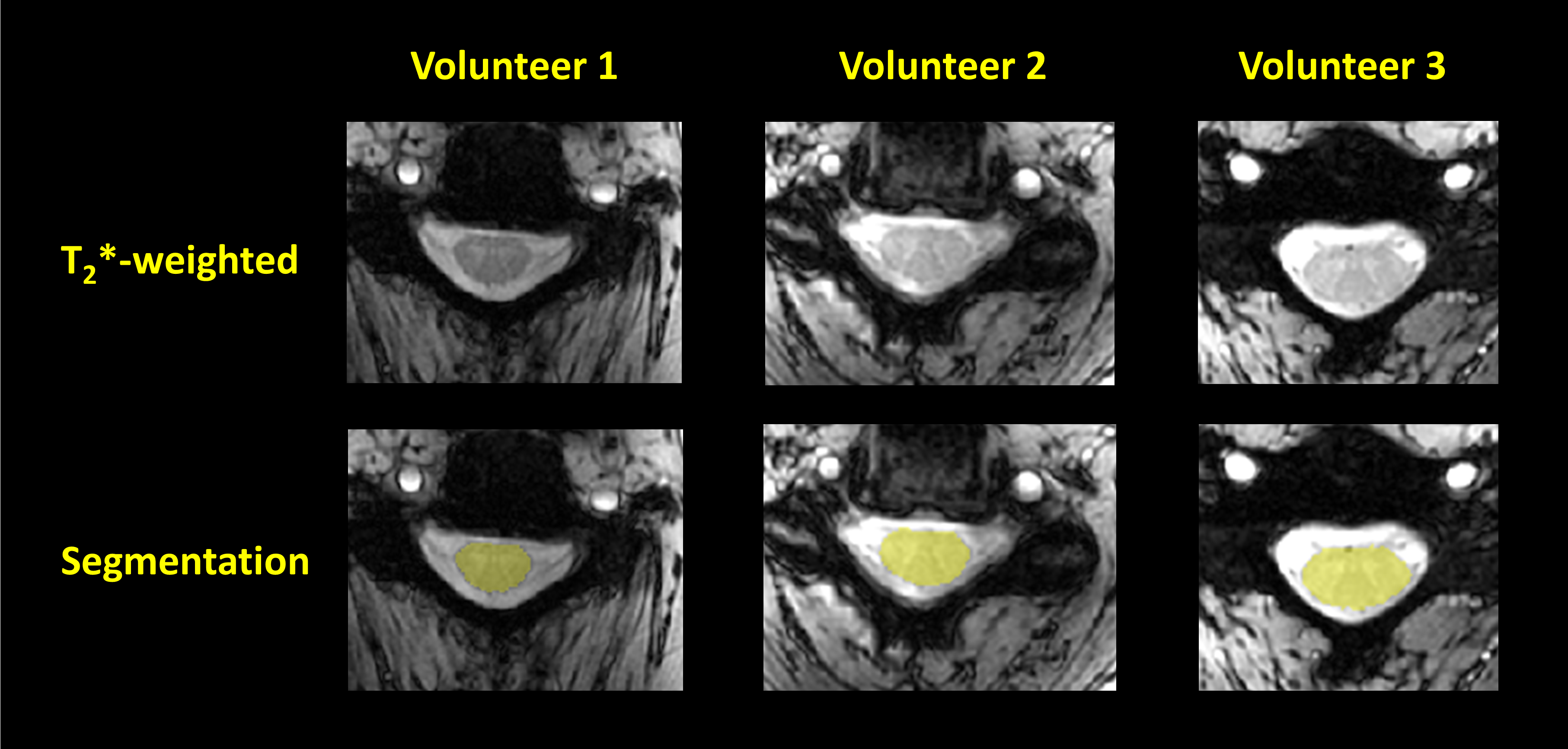
The Deep-learning based spinal cord segmentation module (Deepseg)10 of the spinal cord toolbox11 (SCT) (https://sourceforge.net/projects/spinalcordtoolbox/) was used to segment the cervical spinal cord from the axial images acquired with a voxel size of 0.6 × 0.6 × 3.0 mm3 from three healthy volunteers. Cross-sectional areas (CSA) were calculated from these images at C3-C4 cervical levels using the SCT.
Results
The inter-coil coupling in vivo was lower than -16 dB for all the elements of the array. Figure 1 shows the coil setup and the longitudinal coverage of the coil, which encompasses the C1-C7 cervical levels. The shimmed B1+ map and the corresponding axial T2*-weighted image are shown in Figure 2 (panels A and B). The B1+ shimming routine produced a maximum B1+ value of 15µT for an input power of 200 W per channel, with less than 10% variation within the SC itself. Dorsal and ventral nerve roots, blood vessels, and denticulate ligament were visible on the higher 0.4 x 0.4 mm2 in-plane resolution T2*-weighted images (Figure 3). Figure 4 shows T2*-weighted images from different volunteers. Cross-sectional areas (CSAs) from regions C3-C4 of three healthy volunteers were measured as 93.1 ± 15.8 mm2.Discussion and Conclusions
In this work, we present the feasibility of imaging cervical SC by using a flexible coil design, which allows us to obtain good quality images from different volunteers without the need to retune the coils. The measured S-parameters show that the coil elements are highly decoupled. Cervical SC scans from healthy volunteers demonstrate the performance of the coil. Good image quality was obtained with distinguishable gray/white matter contrast, and visible nerve roots, denticulate ligament, and blood vessels. Cross-sectional area measurements from C3-C4 cervical levels were consistent with previous work on 7T scanners4. Work in progress includes optimizing the acquisition protocol to further improve contrast and decrease sensitivity to motion and B0 inhomogeneities.Acknowledgements
This work was funded by ERC NOMA-MRI 670629.References
1. Barry RL, Vannesjo SJ, By S, Gore JC, Smith SA. Spinal cord MRI at 7T. Neuroimage. 2018 Mar; 168:437-451.
2. Massire A, Taso, M, Besson P, Guye M, Ranjeva JP, Callot V. High-resolution multi-parametric quantitative magnetic resonance imaging of the human cervical cord at 7T. Neuroimage 2016; 143: 58-69.
3. Zhao W, Cohen-Adad J, Polimeni JR, Keil B, Guerin B, Setsompop K, Serano P, Mareyam A, Hoecht P, Wald LL. Nineteen-Channel Receive Array and Four-Channel Transmit Array Coil for Cervical Spinal Cord Imaging at 7T. Magn Reson Med. 2014; 72:291–300.
4. Sigmund EE, Suero GA, Hu C, McGorty K, Sodickson DK, Wiggings GC, Helpern JA. High-resolution human cervical spinal cord imaging at 7T. NMR Biomed. 2012; 25: 891–899.
5. Zhang B, Seifert AC, Kim J-w, Borrello J, Xu J. 7 Tesla 22-channel wrap-around coil array for cervical spinal cord and brainstem imaging. Magn Reson Med. 2017; 78(4):1623-1634.
6. Kraff O, Bitz AK, Kruszona S, Orzada S, Schaefer LC, Theysohn JM, Maderwald S, Ladd ME, Quick HH. An eight-channel phased array RF coil for spine MR imaging at 7 T. Invest Radiol. 2009; 44:734–740.
7. Wu B, Wang C, Krug R, Kelley DA, Xu D, Pang Y, Banerjee S, Vigneron DB, Nelson SJ, Majumdar S, Zhang X. 7T human spine imaging arrays with adjustable inductive decoupling. IEEE Trans Biomed Eng. 2010; 57:397–403.
8. Ruytenberg T, Webb A, Zivkovic I. Shielded‐coaxial‐cable coils as receive and transceive array elements for 7T human MRI. Magn Reson Med 2019; doi: 10.1002/mrm.27964
9. Nehrke K, Bornert P. DREAM ‐ a novel approach for robust, ultrafast, multislice B‐1 mapping. Magn Reson Med. 2012;68:1517–1526.
10. Gros C, De Leener B, Badji A, et al. Automatic segmentation of the spinal cord and intramedullary multiple sclerosis lesions with convolutional neural networks. Neuroimage 2019;184:901–15.
11. De Leener B, Lévy S, Dupont SM, et al. SCT: Spinal Cord Toolbox, an open-source software for processing spinal cord MRI data. Neuroimage 2017;145:24–43.
Figures