1137
Conductive Elastomer for Wearable RF Coils1Institute for Biomedical Engineering, ETH Zurich and University of Zurich, Zurich, Switzerland
Synopsis
Several stretchable conductor concepts have been proposed that rely on a continuous metal phase, rigid or liquid, as conductive path. Conductive elastomers, fundamentally different, form the conductive path through contact between particles such as carbon nano tubes, silver nanowires or silver microparticles. In the present work, we explore the feasibility and performance of MR detection with conductive elastomer coils. Evaluation is performed in terms of Q, SNR and in-vivo imaging. The results indicate that MR receive coils made from conductive elastomer provide good stretchability, adequate electrical performance and promise workflow enhancements as such a coil could even be washed.
Introduction
For many uses of MRI it is desirable to adapt the size and shape of RF coils to each patient’s individual anatomy. To varying degrees, this can be achieved with rigid-adjustable1-3 and flexible4-12 designs. However, for true size adjustment and towards wearable designs, RF coils should additionally be stretchable. Stretchability has been implemented based on conductor length reserve using braided13 or meandering14 copper or conductive thread15,16. A more recent alternative is the use of liquid metal conductors. To form a coil, liquid metal can be printed onto a substrate17 or contained in a stretchable tube18, which simplifies sealing and removes the need for external restoring forces.All of these solutions rely on a continuous metal phase, either solid or liquid, for conduction. Conductive polymers, in contrast, form conductive paths through contact between particles such as carbon nanotubes19-21, silver nanowires22,23 or silver microparticles24 embedded in an elastic polymer matrix25-27. According to percolation theory, above a certain density threshold the randomly distributed particles form a continuous electrical connection and thus render the elastomer conductive28.
Conductive elastomers are an attractive alternative for wearable coil design. While sharing the advantages of liquid-metal tubes they obviate the issue of potential leakage. The dry, inert material would simplify manufacturing and could even permit washable designs. However, the conductivity reached with elastomers is still relatively low by the standards of MRI detection.
Given these promises and potential limitation, in the present work we explore the feasibility and performance of MR detection with conductive elastomer coils.
Methods
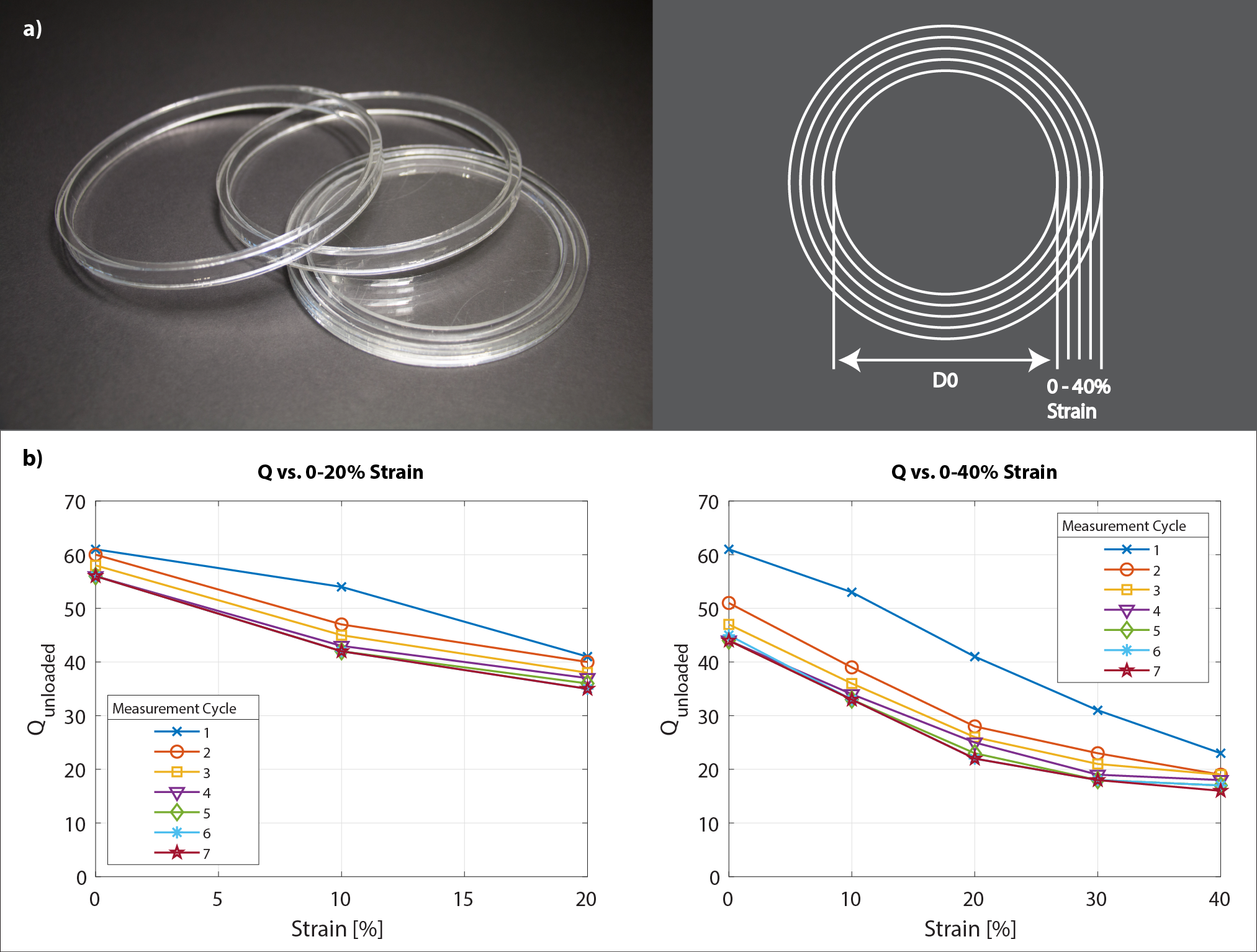
Conductive ElastomerFilaments of a conductive elastomer based on silver microparticles (nanoleq AG, Zurich, Switzerland) were sourced at a diameter of 2 mm. The material is cut to the length of the coil segment and a solderable contact formed by crimping. Heat shrink tubing is applied (Fig.1). The manufacturer specifies the material to be corrosion resistant, heat and cold resistant and washable. The volume resistivity of the material is specified as ρElastomer = 7*10-6 Ωm. At DC this is a factor 417 higher than the resistivity of copper ρCopper = 1.68*10-8 Ωm. At 128 MHz, however, the skin depth of the elastomer δElastomer = 117.7 μm is a factor of ≈20 larger than of copper δCopper = 5.8 μm. For two conductors of the same length l and diameter d (d>2*δElastomer) this results in a resistance that is only ≈20 times larger for the elastomer conductor than for copper, despite the extreme difference in resistivity4.
Wearable Array Construction
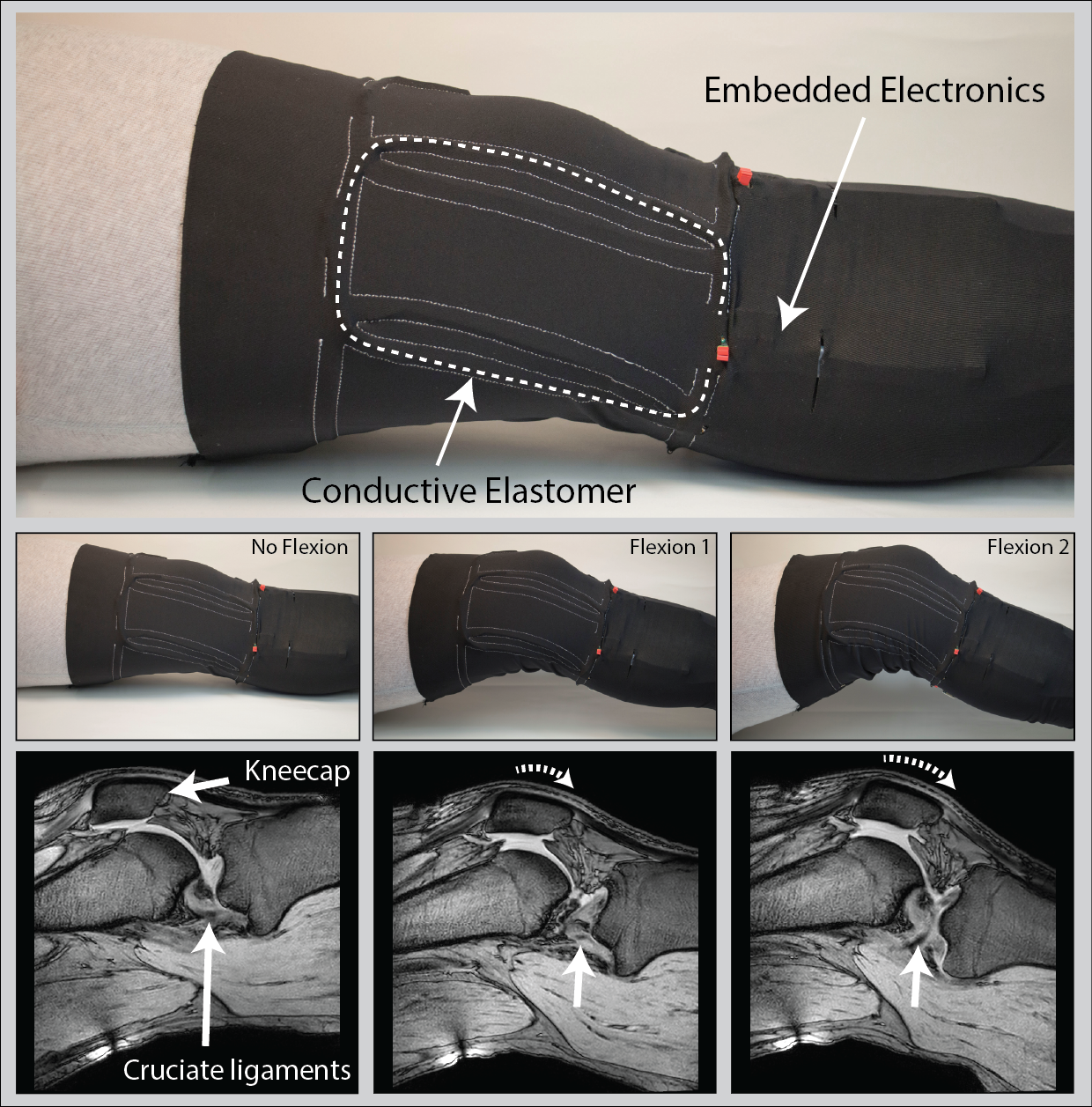
Two layers of common highly elastic athletic pants were sewn onto each other following a pattern that forms stretchable casings that allow insertion of four coil elements in between the two layers (Fig.4). The sewing pattern ensures approximate geometric decoupling which is complemented by preamplifier decoupling. The high-Z preamplifiers with low correlation resistance offer low noise figure at variable loading and π-matching networks accommodate frequency shifts upon stretching1.
Imaging
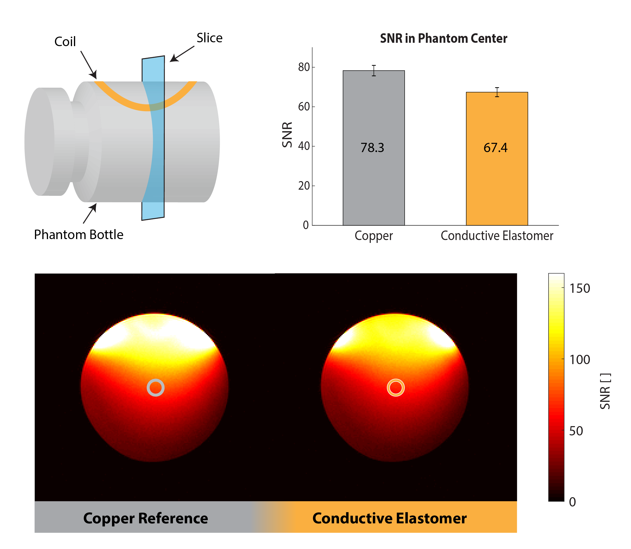
Images were obtained on a Philips 3T Ingenia system. SNR maps were calculated1 from phantom images obtained with an elastomer coil and a copper coil for comparison, both based on conductors of 2 mm diameter (Fig.3). In-vivo images of a healthy volunteer's knee were acquired at 3 different flexion angles (Fig.4) and in a dynamic study with continuous flexion (Fig.5).
Results
The coils' unloaded Q was assessed at 61 before its first strain (Fig.2). Upon strain the coils' Q converges to its final value within ≈ 7 strain cycles. Depending on the maximum strain applied to the conductive elastomer coil the final Q reaches values of 56 and 44 for a maximum repetitive strain of 20% or 40%, respectively. A Qunloaded/Qloaded ≈ 6 is observed by loading with a volunteer’s thigh – sufficient for SNR efficient detection. The SNR in the center of a loading phantom was assessed to be 14% lower for the conductive elastomer coil compared to the copper reference coil, as expected due to the elastomer’s lower conductivity (Fig.3). In-vivo knee images, static (Fig.4) and dynamic (Fig.5), confirm sensitivity and coverage at different flexion angles and when flexed continuously.Discussion
The results of this study indicate that conductive elastomer is in fact a viable material for stretchable MR receive arrays and enables high-quality imaging. The favorable properties of elastomers come at an expense in terms of volume conductivity, which, however, is intrinsically mitigated by concomitant increase in skin depth. Upon repeated stretching by 20%, medium-size coil elements settled at an unloaded Q of approximately 40, which is still well above typical loaded Q at 3T and thus entails only a moderate SNR drawback. When necessary, a natural way of increasing the unloaded Q is to increase the conductor diameter, which was moderate here at 2 mm. Conductive elastomer poses no risk of leakage and is lightweight, easy to handle, and can readily be subject to washing and sanitization. These features make the material very attractive for wearable detection setups in conjunction with on-coil digitization and wireless transmission29–34.Acknowledgements
References
1. J. A. Nordmeyer-Massner, N. De Zanche, and K. P. Pruessmann, “Mechanically adjustable coil array for wrist MRI,” Magn. Reson. Med., vol. 61, no. 2, pp. 429–438, 2009.
2. W. E. Kwok, K. K. Lo, G. Seo, and S. M. S. Totterman, “A volume adjustable four-coil phased array for high resolution MR imaging of the hip,” Magn. Reson. Mater. Physics, Biol. Med., vol. 9, no. 1–2, pp. 59–64, 1999.
3. G. Adriany et al., “A geometrically adjustable 16-channel transmit/receive transmission line array for improved RF efficiency and parallel imaging performance at 7 Tesla,” Magn. Reson. Med., vol. 59, no. 3, pp. 590–597, 2008.
4. J. A. Malko, E. C. McClees, I. F. Braun, P. C. Davis, and J. C. Hoffman, “A flexible mercury-filled surface coil for MR imaging,” Am. J. Neuroradiol., vol. 7, no. 2, pp. 246–247, 1986.
5. J. Rousseau, P. Lecouffe, and X. Marchandise, “A new, fully versatile surface coil for MRI,” Magn. Reson. Imaging, vol. 8, no. 4, pp. 517–523, 1990.
6. F. Jia, H. Yuan, D. Zhou, J. Zhang, X. Wang, and J. Fang, “Knee MRI under varying flexion angles utilizing a flexible flat cable antenna,” NMR Biomed., vol. 28, no. 4, pp. 460–467, 2015.
7. D. Mager et al., “An MRI receiver coil produced by inkjet printing directly on to a flexible substrate,” IEEE Trans. Med. Imaging, vol. 29, no. 2, pp. 482–487, 2010.
8. J. R. Corea et al., “Screen-printed flexible MRI receive coils,” Nat. Commun., vol. 7, p. 10839, 2016.
9. S. S. Vasanawala et al., “Development and Clinical Implementation of Very Light Weight and Highly Flexible AIR Technology Arrays,” in Proceedings of the 24th Annual Meeting of the ISMRM, 2016, pp. 3–5.
10. B. Zhang, D. K. Sodickson, and M. A. Cloos, “A high-impedance detector-array glove for magnetic resonance imaging of the hand,” Nat. Biomed. Eng., vol. 2, no. August, pp. 1–8, 2018.
11. L. Nohava et al., “Flexible multi-turn multi-gap coaxial RF coils ( MTMG-CCs ): design concept and bench validation,” Proc. 27th Annu. Meet. ISMRM, Montréal, Canada, nr. 3903, pp. 3–5, 2019.
12. M. Obermann et al., “Ultra-flexible and light-weight 3-channel coaxial transmission line resonator receive-only coil array for 3T,” Proc. 27th Annu. Meet. ISMRM, Montréal, Canada, vol. 6, no. I, pp. 2018–2019, 2019.
13. J. A. Nordmeyer-Massner, N. De Zanche, and K. P. Pruessmann, “Stretchable coil arrays: Application to knee imaging under varying flexion angles,” Magn. Reson. Med., vol. 67, no. 3, pp. 872–879, 2012.
14. B. Gruber and S. Zink, “Anatomically adaptive local coils for MRI Imaging – Evaluation of stretchable antennas at 1.5T,” Proc. 24th Annu. Meet. ISMRM, p. 543, 2016.
15. J. Vincent and J. Rispoli, “Stretchable and Flexible Conductive-Thread Based Radiofrequency Coils for Magnetic Resonance Imaging,” Proc. Intl. Soc. Mag. Reson. Med. 27, p. 1490, 2019.
16. B. Kahraman Agir, B. Bayrambas, K. Yegin, and E. Ozturk Isik, “Wearable and stretchable surface breast coil,” Proc. Intl. Soc. Mag. Reson. Med. 27, pp. 2–4, 2019.
17. M. Varga et al., “Adsorbed Eutectic GaIn Structures on a Neoprene Foam for Stretchable MRI Coils,” Adv. Mater., vol. 29, no. 44, pp. 1–7, 2017.
18. A. Port et al., “Liquid metal in stretchable tubes: A wearable 4-channel knee array,” Proc. Intl. Soc. Mag. Reson. Med. 27, p. 1114, 2019.
19. M. K. Shin, J. Oh, M. Lima, M. E. Kozlov, S. J. Kim, and R. H. Baughman, “Elastomeric conductive composites based on carbon nanotube forests,” Adv. Mater., vol. 22, no. 24, pp. 2663–2667, 2010.
20. D. J. Lipomi et al., “Skin-like pressure and strain sensors based on transparent elastic films of carbon nanotubes,” Nat. Nanotechnol., vol. 6, no. 12, pp. 788–792, 2011.
21. T. Yamada et al., “A stretchable carbon nanotube strain sensor for human-motion detection,” Nat. Nanotechnol., vol. 6, no. 5, pp. 296–301, 2011.
22. F. Stauffer and K. Tybrandt, “Bright Stretchable Alternating Current Electroluminescent Displays Based on High Permittivity Composites,” Adv. Mater., pp. 7200–7203, 2016.
23. V. Martinez, F. Stauffer, M. O. Adagunodo, C. Forro, J. Vörös, and A. Larmagnac, “Stretchable Silver Nanowire-Elastomer Composite Microelectrodes with Tailored Electrical Properties,” ACS Appl. Mater. Interfaces, vol. 7, no. 24, pp. 13467–13475, 2015.
24. F. Stauffer et al., “Skin Conformal Polymer Electrodes for Clinical ECG and EEG Recordings,” Adv. Healthc. Mater., vol. 7, no. 7, pp. 1–10, 2018.
25. Y. L. Park, Soft Wearable Robotics Technologies for Body Motion Sensing. Elsevier Inc., 2016.
26. Y. P. Mamunya, V. V Davydenko, P. Pissis, and E. V Lebedev, “Electrical and thermal conductivity of polymers filled with metal powders,” Eur. Polym. J., vol. 38, pp. 1887–1897, 2002.
27. G. Harsanyi, “Polymer films in sensor applications: a review of present uses and future possibilities,” Sens. Rev., vol. 20, no. 2, p. 98, 2000.
28. S. Choi, S. I. Han, D. Kim, T. Hyeon, and D. H. Kim, “High-performance stretchable conductive nanocomposites: Materials, processes, and device applications,” Chem. Soc. Rev., vol. 48, no. 6, pp. 1566–1595, 2019.
29. A. Port et al., “Towards wearable MR detection: A stretchable wrist array with on-body digitization,” in Proc. Joint Annual Meeting ISMRM-ESMRMB, Paris, France, 2018, p. 17.
30. B. Sporrer et al., “A Fully Integrated Dual-Channel On-Coil CMOS Receiver for Array Coils in 1.5-10.5 T MRI,” IEEE Trans. Biomed. Circuits Syst., 2017.
31. K. Aggarwal et al., “A Millimeter-Wave Digital Link for Wireless MRI,” IEEE Trans. Med. Imaging, 2016.
32. G. Scott, S. Vasanawala, F. Robb, P. Stang, and J. Pauly, “Pilot Tone Software Synchronization for Wireless MRI Receivers,” in Proc. Joint Annual Meeting ISMRM-ESMRMB, Paris, France, 2018, pp. 4–6.
33. A. Reykowski et al., “High Precision Wireless Clock Recovery for On-Coil MRI Receivers Using Round- Trip Carrier Phase Tracking,” in Proc. Joint Annual Meeting ISMRM-ESMRMB, Paris, France, 2018, pp. 2–5.
34. C. Vassos, F. Robb, S. Vasanawala, J. Pauly, and G. Scott, “Characterization of In-Bore 802.11ac Wi-Fi Performance,” in Proc. Intl. Soc. Mag. Reson. Med. 27, 2019.
Figures