1136
A Hydraulically Operated Wireless RF Switch to Control Antenna Tuning in MR-Mediated Radiofrequency Ablation
Jerome L. Ackerman1,2, Erez Nevo3, and Abraham Roth3
1Martinos Center for Biomedical Imaging, Department of Radiology, Massachusetts General Hospital, Charlestown, MA, United States, 2Department of Radiology, Harvard Medical School, Boston, MA, United States, 3Robin Medical, Inc., Baltimore, MD, United States
1Martinos Center for Biomedical Imaging, Department of Radiology, Massachusetts General Hospital, Charlestown, MA, United States, 2Department of Radiology, Harvard Medical School, Boston, MA, United States, 3Robin Medical, Inc., Baltimore, MD, United States
Synopsis
In magnetic resonance mediated radiofrequency ablation (MR-RFA) the RF energy for the ablation is captured by a wire antenna placed in the scanner bore, and channeled to the ablation needle. There are no external wired connections. The effective length of the antenna is adjusted physically or electrically to be resonant with the scanner RF to maximize energy capture. To suppress heating when desired, the antenna must be detuned. An electronic switch to do so reduces antenna efficiency, but a simple wireless hydraulically activated mechanical switch maintains full antenna efficiency and achieves high on-off ratio.
Introduction
MR-mediated RF ablation employs wireless Faraday induction to couple RF energy from the scanner’s body RF coil to a conductive device (e.g., a wire) connected to a needle inserted into the treatment zone.1 There are no external connections to a generator; the scanner provides the RF energy for the ablation. The effectiveness of the wire’s power transfer efficiency depends on its electrical network properties, the Larmor frequency, and the relative geometry of the wire and the scanner transmit coil. Typically, the wire would be tuned to the scanner Larmor frequency by cutting to the appropriate physical length, or adjusting its electrical length (for example with a series variable capacitor). When ablation heating is not desired (e.g., during anatomic scans) the antenna must be detuned. During ablation (by running a scan with high RF dose) it may be desirable to switch the tuning to limit or control the heating by time proportioning. Electronic connections to the antenna to achieve switching between the tuned and detuned states tend to lower the antenna Q, thereby drastically reducing the heating efficiency in the tuned state, while not completely suppressing heating in the detuned state. We designed a simple nonmagnetic mechanical switch that is operated by a hydraulic connection. The actuator is placed outside the magnet and is connected to the switch by a small plastic tube containing water.Methods
PIN diode switches operated by nonmagnetic batteries were constructed to alter the electrical length of the antenna. The mechanical switch was constructed from beryllium copper finger stock. The hydraulic line consisted of a 7.5 m long 6.35 mm diameter high density polyethylene tube filled with water. The tube ends were terminated in Dynalon 1.5 mL polyethylene pipets (ThermoFisher, Waltham, MA, USA) which are constructed in a bellows shape permitting them to function as pressure-driven linear actuators. One actuator was mounted against one mechanical switch contact. The other actuator was driven by a Magnetic Sensor Systems MSS-16-264-23-12VS solenoid (McMaster-Carr, Robbinsville, NJ, USA) placed away from the magnet. Power for the solenoid was provided by a 12VDC sealed lead-acid battery and controlled by a manual switch, a remote contact closure or a wireless radio link. The temperature of the ablation needle tip was monitored by a Neoptix (Québec City, QUE, Canada) T1 fiber optic temperature probe. The temperature probe was connected to a Neoptix Reflex signal conditioner. Temperature-time profiles were recorded using the serial interface of the signal conditioner. The Reflex signal conditioner provides an analog voltage output proportional to temperature. This voltage was compared to a voltage set by a 10-turn potentiometer in a simple on-off controller connected to the RF switch wired actuation port or to the wireless transmitter. MR-RFA heating experiments were conducted in a Siemens (Erlangen, Germany) Trio 3 T MRI scanner using a polyacrylic acid (PAA) gel phantom into which the ablation needle was inserted.Results
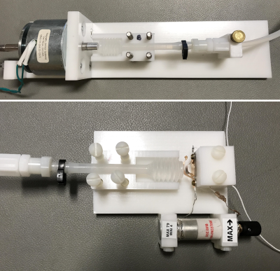
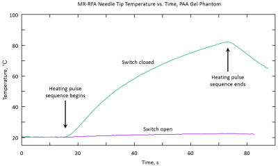
Figure 1 is a diagram of the hydraulic system. Figure 2 shows photos of the solenoid and RF switch ends of the hydraulic line. Inserting a PIN diode switch in series with the antenna to change its effective electrical length always resulted in a significant reduction in heating when the diode was driven on, and did not fully eliminate heating when the diode was driven off. The mechanical switch enabled full heating when closed and complete suppression of heating when open. Figure 3 shows a typical heating run in which the RFA needle tip is placed in the PAA gel. The hydraulically operated switch can cycle between open and closed in under 1 secondDiscussion
The mechanical RF switch exhibits a far better on-off ratio than the PIN diode switch. The mechanical switch requires no wired connections entering the magnet for actuation, thereby avoiding the potential for inadvertent heating and RF noise conduction. However, it requires a water-filled plastic tube connection, which is somewhat awkward because of the stiffness of the tube. A thinner walled tube was more flexible, but the increased wall compliance resulted in a loss of force transfer to the switch actuator. A smaller diameter tube resulted in higher flow resistance, with a concomitant loss of force transfer.Conclusions
The hydraulically driven mechanical RF switch was found to be an effective means to tune or detune the wire antenna for MR-mediated radiofrequency ablation. It did not introduce any noise into the scanner’s receivers. Because it is not metallic and essentially nonconductive, it should pose no risk for patients. It may prove useful for other interventional technologies that utilize RF energy derived from the scanner.2Acknowledgements
Funding was provided by grant R44CA203276 from the National Cancer Institute.References
- Hue Y-K, Guimaraes AR, Cohen O, Nevo E, Roth A, Ackerman JL. Magnetic resonance mediated radiofrequency ablation. IEEE Trans Med Imaging 2018; 37: 417-427.
- Cohen O, Zhao M, Nevo E, Ackerman JL. MR coagulation: a novel minimally invasive approach to aneurysm repair. J Vasc Interv Radiol 2017; 28: 1592-1598.
Figures

Figure 1. Diagram of hydraulically
operated wireless RF switch. The pipets act as reversible linear actuators when
pressurized with water or compressed by an external axially applied force. The
solenoid is placed far from the magnet, and the switch is in the magnet. The
switch contacts are made from beryllium copper finger stock. The hydraulic line
is 7.5 m long and 6.35 mm outside diameter polyethylene tubing.

Figure 2. Photos of hydraulically
operated wireless RF switch components. Covers have been removed to show the
bellows. Top: the solenoid drives the actuator bellows pipet. Bottom: the bellows
pipet compresses the switch leaflets to close the circuit when the solenoid is
activated. The antenna is comprised of 30 AWG silver plated Teflon insulated
wire. The capacitor, a Sprague-Goodman (Westbury, NY, USA) SGNMNC3708E nonmagnetic
high voltage 3–70 pF 78-turn variable capacitor (measured limits 4-79 pF) is in
series with the antenna to provide fine adjustment of its electrical length.

Figure 3. MR-RFA needle tip
temperature vs. time during 1 min heating (high SAR) scan. Green: hydraulic RF
switch closed, antenna tuned. Purple: switch open, antenna detuned.