1135
Measurement-based safety assessment, prediction and mitigation of RF induced implant heating with parallel transmission: temperature matrix1Physikalisch-Technische Bundesanstalt, Berlin, Germany
Synopsis
A Measurement-based Temperature-Matrix approach is presented that enables a fast, patient and exam specific estimation and mitigation of RF hazards of implants. Various locations in phantom are tested using an 8-channel (300MHz) implant safety testbed. Heating reduction Based on T-Matrix Measurements resulted >3 times heating reduction vs. circularly-polarized mode and >19 times vs. worst-case mode. 2-channel MRI (3T) feasibility experiments using high temperature resolution showed good correlation with transmitted power. In addition, T-matrix-based temperature increase predictions successfully demonstrated. As summary, an easy to implement, cheap, sensor-based method, the T-matrix, to investigate, characterize and mitigate RF heating of implants is introduced.
Introduction
Parallel transmission (pTx) is an effective method to substantially reduce RF induced heating in medical implants1–3. Simulation and in-vitro-based mitigation approaches cannot provide a patient and exam specific assessment. Approaches that rely on integrated sensors in and around the implant allow for a patient-specific, real-time mitigation, while simultaneously the sensors provide an online safety monitoring4–6. In this work, we introduce the temperature matrix (T‑matrix), a pTx monitoring and mitigation approach based on a single thermistor (0.1$) that can easily be integrated within the implant. This approach enables a fast, patient and exam specific estimation and mitigation of RF hazards, in principle without the need for prior simulations or in vitro testing. Feasibility is demonstrated by applying the T-matrix for heating prediction and mitigation using an 8-channel pTx coil at 300MHz in an implant-safety testbed and a 2-channel body coil inside a 3T MRI scanner.Methods
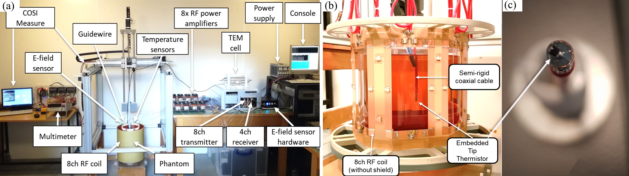
Instrumentation: An implant safety testbed with an 8-channel 7T pTx RF coil6 and a cylindrical PVP based phantom is used for benchtop experiments (Fig.1a-b). A semi-rigid coaxial cable with an uninsulated tip is used as a guidewire substitute (Fig. 1b). An NTC thermistor (NCP18XH103F03RB, Murata) is connected between inner and outer conductor at the tip of the cable (Fig. 1c).T-matrix: Tip heating impulse responses based on a complex voltage excitation vector $$$\vec{u}$$$(n) of an n-channel array are measured and used to calculate the Hermitian T-matrix $$$\overset{\text{$\leftrightarrow$}}{T_M}$$$: $$\Delta T = \vec{u}^H\overset{\text{$\leftrightarrow$}}{T_M}\vec{u} \label{eq:Tmat} $$
To determine $$$\overset{\text{$\leftrightarrow$}}{T_M}$$$, RF pulses with phase differences 0° (i<j) or 90° (i>j) are applied to channels i, j and the corresponding temperature rise, ΔTij, is recorded. In order to demonstrate a proof of concept mitigation of RF induced heating, an orthogonal projection (OP) mode was applied, which is the projection of the circular polarized (CP) vector onto the subspace orthogonal to the $$$\overset{\text{$\leftrightarrow$}}{T_M}$$$ eigenvector with the largest eigenvalue. OP allows to mitigate RF induced heating, while maintaining sufficient B1+ homogeneity for imaging6,7. The worst case (WC) is defined using the phases of the $$$\overset{\text{$\leftrightarrow$}}{T_M}$$$ eigenvector with the largest eigenvalue and equal amplitudes, which corresponds to the worst possible RF induced heating using a pTx transmission system with limited forward power per channel.
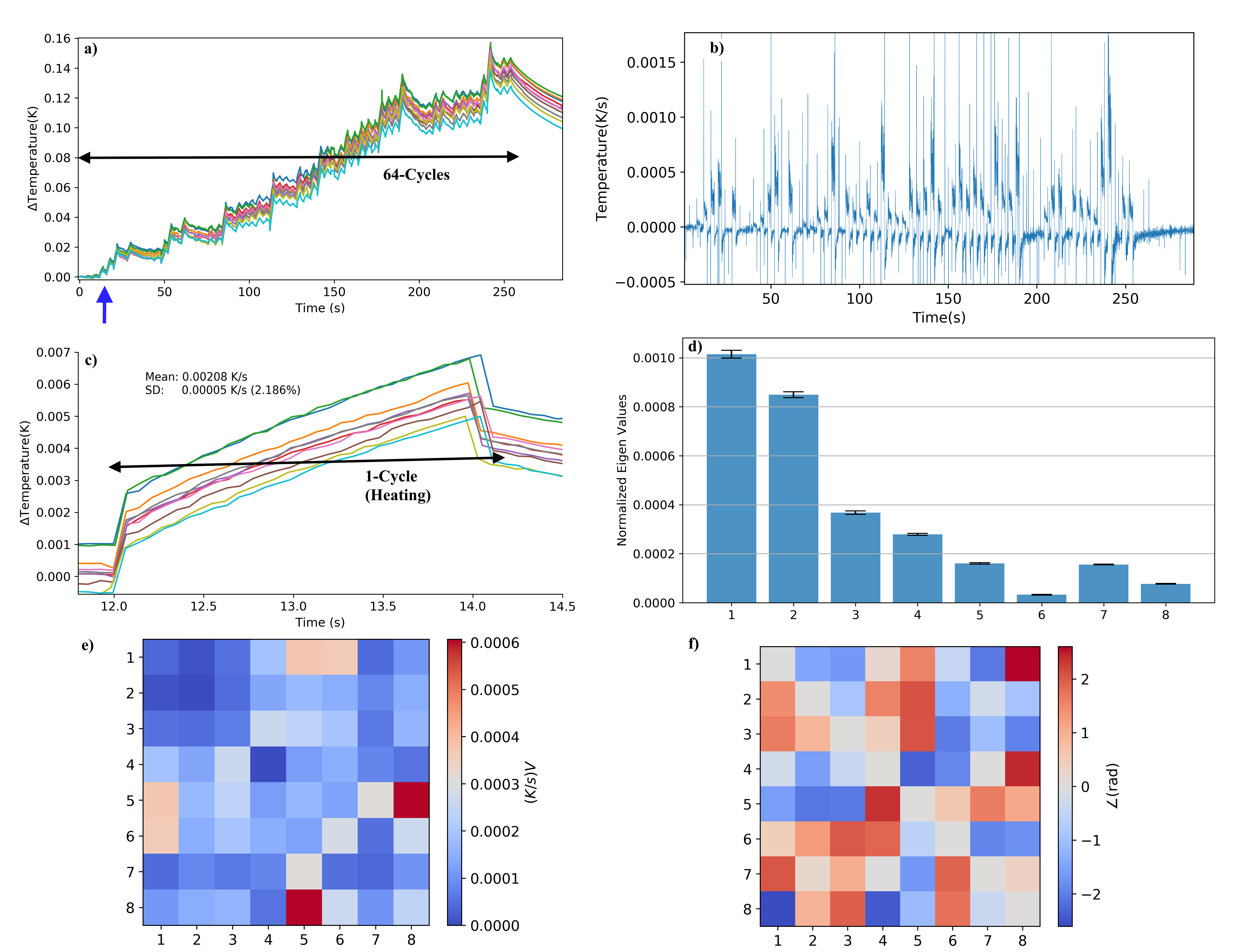
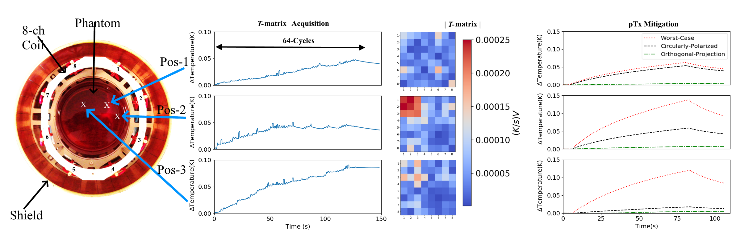
Benchtop Experiments (300MHz): Repeatability was tested with 10 $$$\overset{\text{$\leftrightarrow$}}{T_M}$$$ measurements at the same location (64 cycles: 2s RF heating/2s cooling). The T-matrix (64 cycles: 1s RF-heating/1s cooling) was evaluated on three locations within the phantom. The transmitted average power over the acquisition window was 3.14W. RF heating experiments in CP, OP and WC mode were performed with the same total forward power of 2.06W at Pos-1, 2.47W at Pos-2 and 2.41W at Pos-3 (Fig.3).
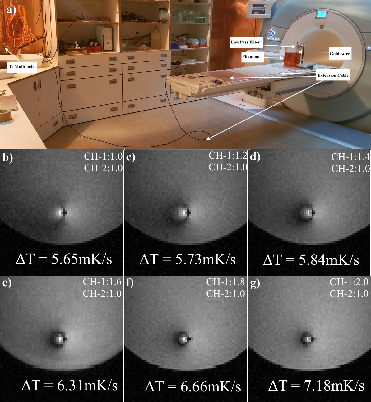
MRI Experiments (3T): To investigate the feasibility of the $$$\overset{\text{$\leftrightarrow$}}{T_M}$$$ concept under pulsed MRI conditions, a 3T scanner (Siemens, Verio) with a 2-channel body coil (quadrature splitter of the system was removed, and two ports were connected to a pTx system) was utilized Fig.4a. A conventional GRE sequence was used (TR:15ms, pulse length=2ms) to determine the relation between pulsed power vs. temperature increase at the tip.
Results
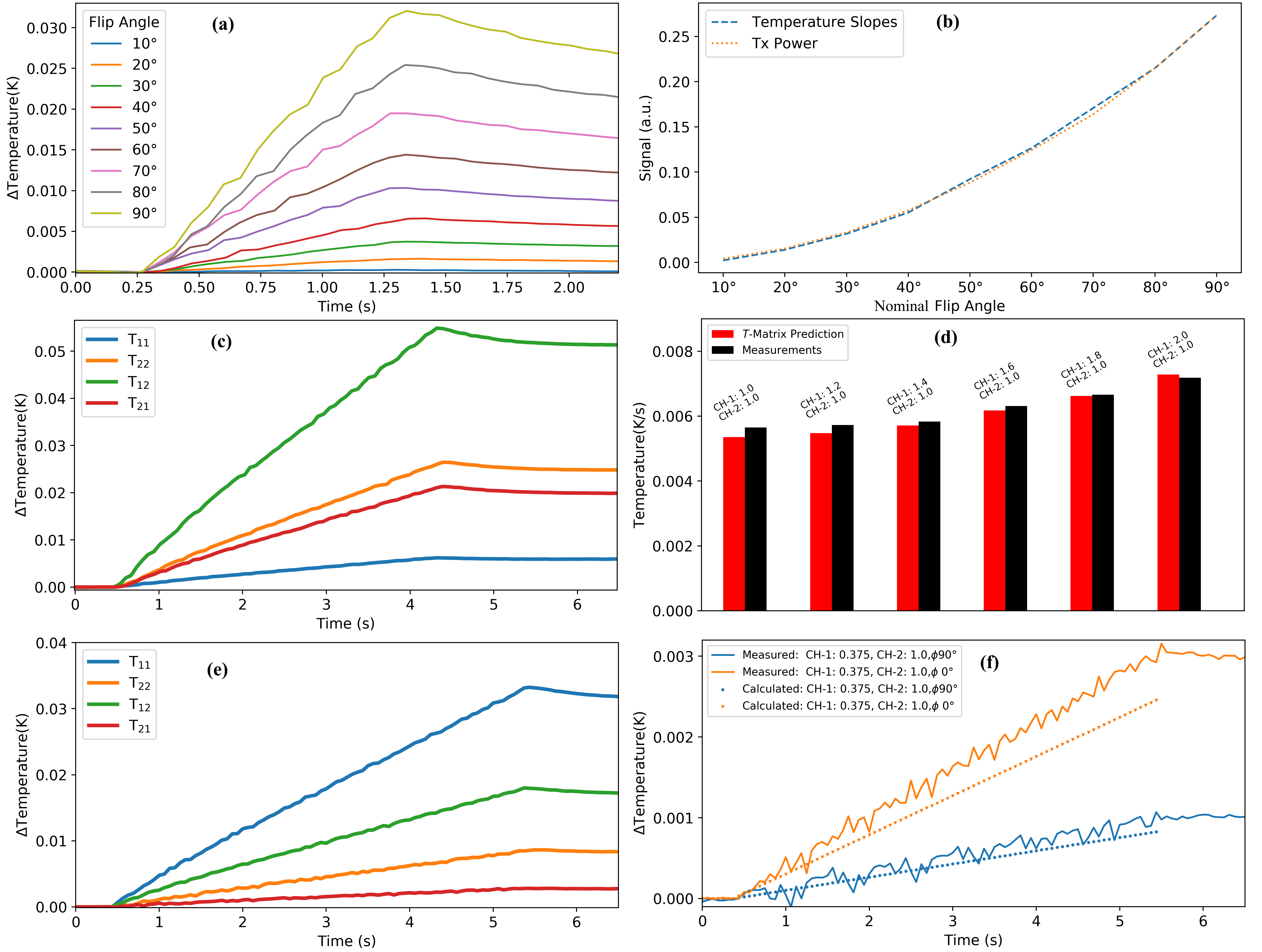
Benchtop Experiments (300 MHz): The temporal resolution of the thermistor reading was ~70ms with a temperature resolution of ~100μK. Repeatability experiments showed <3% standard deviation in slopes and eigenvalues for 10 $$$\overset{\text{$\leftrightarrow$}}{T_M}$$$ measurements (Fig.2). was acquired in 128s with a total temperature rise of <0.1°C at the guidewire tip. Based on the $$$\overset{\text{$\leftrightarrow$}}{T_M}$$$, the calculated OP mode was able to substantially reduce RF induced heating at the guidewire tip at all three locations (>3 times vs. CP mode and >19 times vs. WC mode, Fig. 3).MRI Experiments (3T): MR B1+ image artifacts due to the induced current on the guidewire are displayed in Fig. 4b-g. The temperature increase during a 1s GRE sequence correlates well with transmitted power (Fig. 5a-b), demonstrating the feasibility of using the thermistor in MR experiments. $$$\overset{\text{$\leftrightarrow$}}{T_M}$$$ was acquired at two positions (Figs. 5c,e) in a total of 32s and with an overall temperature increase at the tip of <0.1°C. $$$\overset{\text{$\leftrightarrow$}}{T_M}$$$ contains the full system information and can also be used to predict heating. These predictions correlate well with actual measurements for different pTx driving conditions changing both amplitude (Fig. 5d) and phase (Fig. 5f).
Discussion
The T-matrix can be acquired with good repeatability and speed, requiring only low flip angles. The pTx-based method is able to detect, predict and mitigate guidewire tip temperatures as demonstrated for a 2-channel body-coil at 3T and an 8-channel pTx RF coil for 7T. Based on temperature measurements (not fields or currents), it allows to directly monitor and manage the applied thermal dose9. In future experiments more implant locations, implant orientations and implant geometries will be tested with the introduced method. Furthermore, B1+ homogeneity will be included in the cost function to reduce tip heating.Conclusions
An easy to implement, sensor-based method, the T-matrix, to investigate, characterize and mitigate RF heating of implants is introduced. The technique is fast and does not require additional simulations or prior in vitro testing. It is thus attractive for pTx based temperature control and monitoring of implant temperatures for patient-specific and exam-specific safety assessments.Acknowledgements
This work was funded by the EMPIR grant 17IND01 MIMAS. The EMPIR initiative is co- funded by the European Union’s Horizon 2020 research and innovation program and the EMPIR participating states.References
1. Eryaman Y, Guerin B, Akgun C, et al. Parallel transmit pulse design for patients with deep brain stimulation implants. Magn Reson Med. 2015;73(5):1896-1903.
2. McElcheran CE, Golestanirad L, Iacono MI, et al. Numerical Simulations of Realistic Lead Trajectories and an Experimental Verification Support the Efficacy of Parallel Radiofrequency Transmission to Reduce Heating of Deep Brain Stimulation Implants during MRI. Sci Rep. 2019;9(1).
3. Guerin B, Angelone LM, Dougherty D, Wald LL. Parallel transmission to reduce absorbed power around deep brain stimulation devices in MRI: Impact of number and arrangement of transmit channels. Magn Reson Med. 2020;83(1):299-311.
4. Etezadi-Amoli M, Stang P, Kerr A, Pauly J, Scott G. Controlling radiofrequency-induced currents in guidewires using parallel transmit. Magn Reson Med. 2015;74(6):1790-1802.
5. Silemek B, Acikel V, Oto C, et al. A temperature sensor implant for active implantable medical devices for in vivo subacute heating tests under MRI. Magn Reson Med. 2018;79(5).
6. Winter L, Seifert F, Hoffmann W, et al. Parallel transmission medical implant safety testbed: First application using time-domain E-field probes to measure and mitigate RF induced currents. Proc . ISMRM 2019:0728
7. Seifert F, Weidemann G, Ittermann B. Q matrix approach to control implant heating by transmit array coils. Proc. ISMRM 2015:3212.
8. Han H, Moritz R, Oberacker E, Waiczies H, Niendorf T, Winter L. Open Source 3D Multipurpose Measurement System with Submillimetre Fidelity and First Application in Magnetic Resonance. Sci Rep. 2017;7(1):13452.
9. Van Rhoon GC, Samaras T, Yarmolenko PS, Dewhirst MW, Neufeld E, Kuster N. CEM43°C thermal dose thresholds: A potential guide for magnetic resonance radiofrequency exposure levels? Eur Radiol. 2013;23(8):2215-2227.
Figures