1134
Single channel non-linear breast gradient coil for diffusion encoding1Department of Radiology, Medical Physics, University of Freiburg, University Medical Center, Freiburg, Germany, 2Medical Physics in Radiology, German Cancer Research Center, Heidelberg, Germany, 3Department of Radiology, MR Physics, University Medical Center Erlangen, Erlangen, Germany, 4Junior Group Medical Imaging and Radiology – Cancer Prevention, German Cancer Research Center (DKFZ), Heidelberg, Germany
Synopsis
The aim of this project is to design and implement a non-linear single channel breast gradient coil for diffusion encoding. Initial field maps of the prototype implementation are shown. The prototype should allow to generate gradient strengths between 1 and 3.6 [T/m].
Introduction
Local gradient coils allow for enhanced performance in terms of both, gradient amplitude and switching rate. This led to a renaissance of dedicated head gradient insert coils in the recent years [1,2]. The female human breast is another well-suited target for a dedicated gradient coil due to the fact that it can be partially enclosed [3-5]. In this abstract we report on the implementation of a dedicated non-linear single channel breast coil for diffusion encoding. We aim to achieve gradient strengths beyond 1 [T/m].Methods
One single wire layout was optimized for maximum gradient strength, rather than for homogeneity. A boundary element method similar to the method presented in [6] was implemented in COMSOL Multiphysics (COMSOL AB, Stockholm, Sweden). During the design process multiple current carrying surfaces were compared. This included single breast cups with- and without different rim shapes and a double cup surfaces. The cup size was chosen to include a large fraction of the female population. Besides the balance of force and torque, an additional constraint was added to enforce gradient homogeneity within each coronal slice. This is expected to enable an efficient acquisition of diffusion-encoded images due to low variations of b-values within each slice.A coil former was designed in Autodesk Inventor (Autodesk Inc., San Rafael, Ca, USA) and 3D printed using a powder bed and ink-jet head 3D printer (ZPrinter 450, 3D Systems, Rock Hill, SC, USA). A square profiled Litz wire containing 240 strains, each of diameter 0.2mm (Rudolf Pack GmbH, Gummersbach, Germany) was manually inserted into printed grooves.
The final coil will be cast under vacuum in epoxy resin. Water cooling will be incorporated for removing the excess heat. The final coil is planned to be used with currents up to 625A.
Phase difference maps were measured on a 3T system, (Siemens Healthineers, Erlangen, Germany) equipped additional gradient power amplifiers (GPAs) (IECO, Helsinki, Finland). The additional GPAs are controlled by custom interface hardware and pulse sequences were programmed in the open source pulse sequence framework Pulseq [7,8]. The body RF coil was used for excitation and signals were received using a flexible 4Ch surface coil.
Results
The resulting current carrying surface with iso-contours of the stream functions is depicted in Fig.1. In this design the sensitivity in the target volume varies between 1.7 and 5.77 [mT/m/A]. With an available current of 680A a gradient strength of 1.06 [T/m] can be achieved close to the chest wall and 3.6 [T/m] at the bottom of the cup. A simulated inductance of 65.5 [μH] closely agrees with the measured value of 66.1 [μH]. The CAD design of the two parts of the coil former is shown in Fig.2. Fig.3 depicts the coil formed during coil winding. Measured phase difference maps are displayed in Figures 4 and 5 and closely agree with calculated fields (data not shown).Discussion
The gradient amplitude of the presented design is mainly limited by the achievable wire cross section. Therefore a multi-layer design is expected to solve this issue and further enhance the gradient strength. Handling of Litz wire is quite convenient for prototyping but the filling factor of the cross sections is only about 60%. Therefore a solid wire may be used in future implementations, expected to widthstand higher currents.A single gradient channel does not allow for encoding directional information in diffusion imaging. The aim of this project, however, is to achieve the highest possible diffusion encoding using only one single channel. In addition, tumors in the female breast usually do not show anisotropic behaviour.
An estimate of the electric fields predict that peripheral nerve stimulation (PNS) will not be a limiting factor for this coil. This will be validated experimentally in future studies in vivo.
Measured phase difference maps are noisy due to the shielding effects of the conductors. A dedicated transmit/receive coil for the use within this gradient coil is currently being constructed.
Acknowledgements
Deutsche Forschungsgemeinschaft (DFG) - Project number ZA 422/5-1References
[1] SK Lee MRM 2016 76:1939-50.
[2] M Weiger MRM 2018 79:3256-66
[3] SA Maier, MRM 1998;39:392–401.
[4] SM Moon, MRM 2011;65:863–872.
[5] HS Lopez, JMR 2009;199:48 –55.
[6] F Jia, JMR 2017;281:217-228.
[7] KJ Layton, MRM 2016;77:1544–1552.
[8] http://pulseq.github.io/
Figures
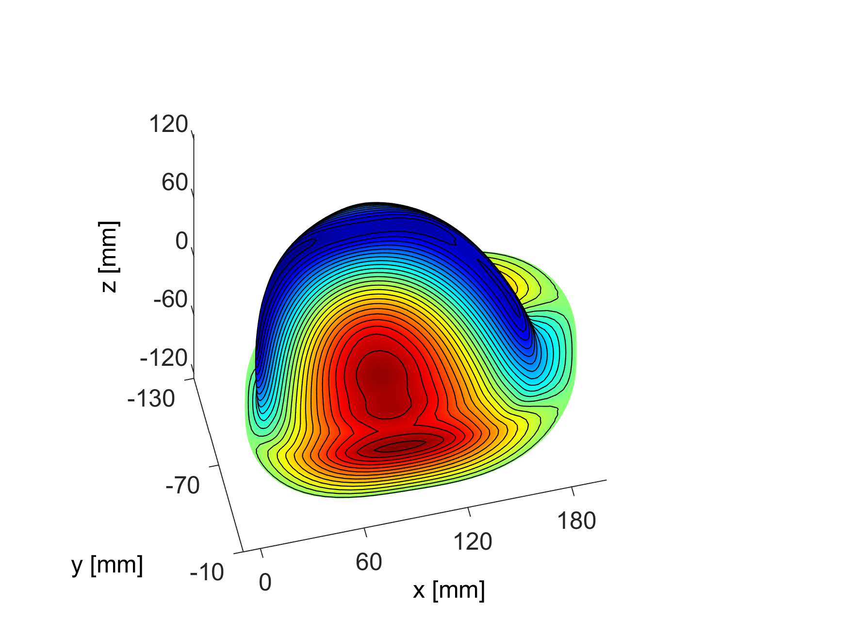
Figure 1: Stream function on current carrying surface:
The final surface of a surface study can be analytically described by a super ellipsoid which is cut by a cylinder. From this cylinder is only a super elliptic cut-out left.The iso-contours of the stream function depict the wire paths which still have to be interconnected to form a continuous single conductor winding.
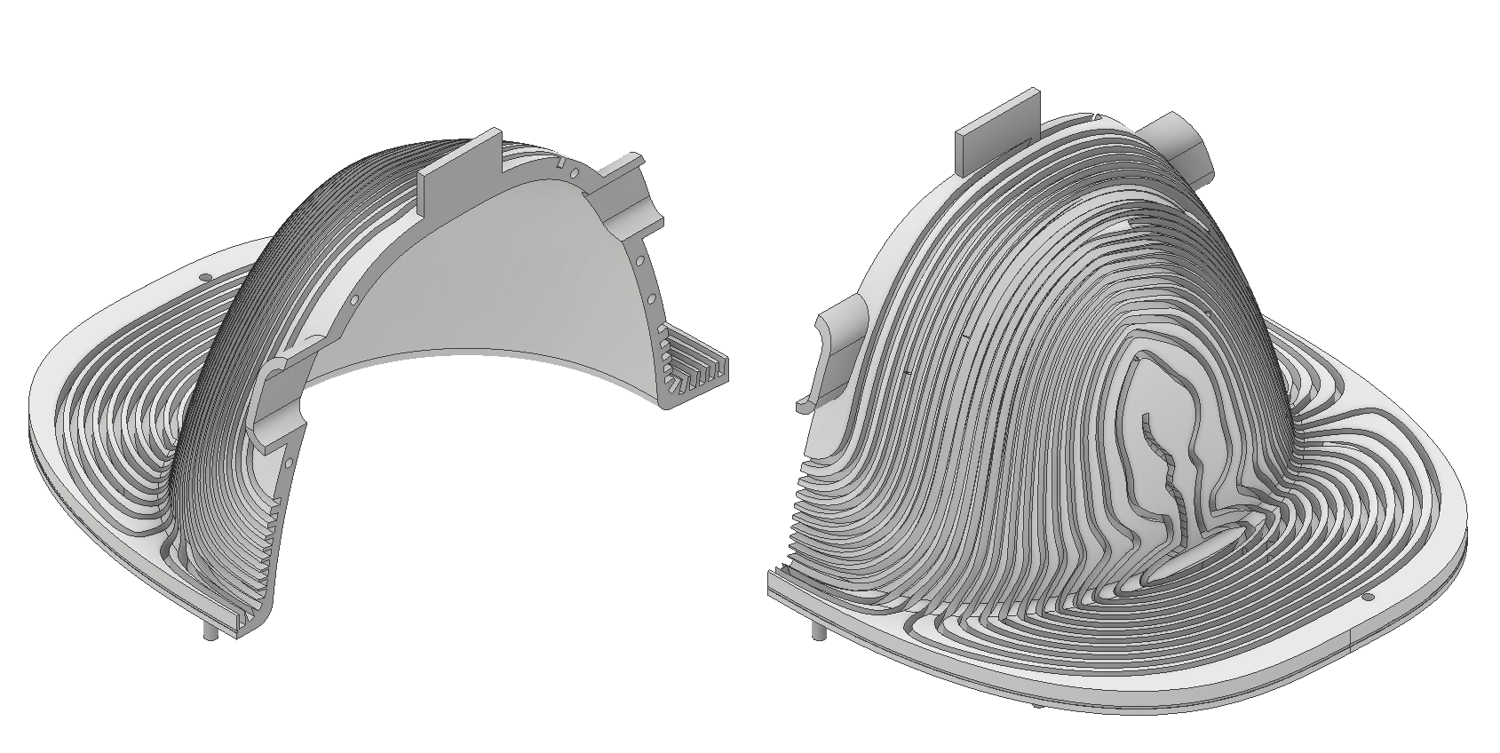
Figure 2: CAD design of the coil carrier
The coil carrier was 3D printed in two parts due to the limitation of the printing volume. Besides the grooves for the wire, there are features for alignment of the two parts and two openings for feeding cables of the RF coil.
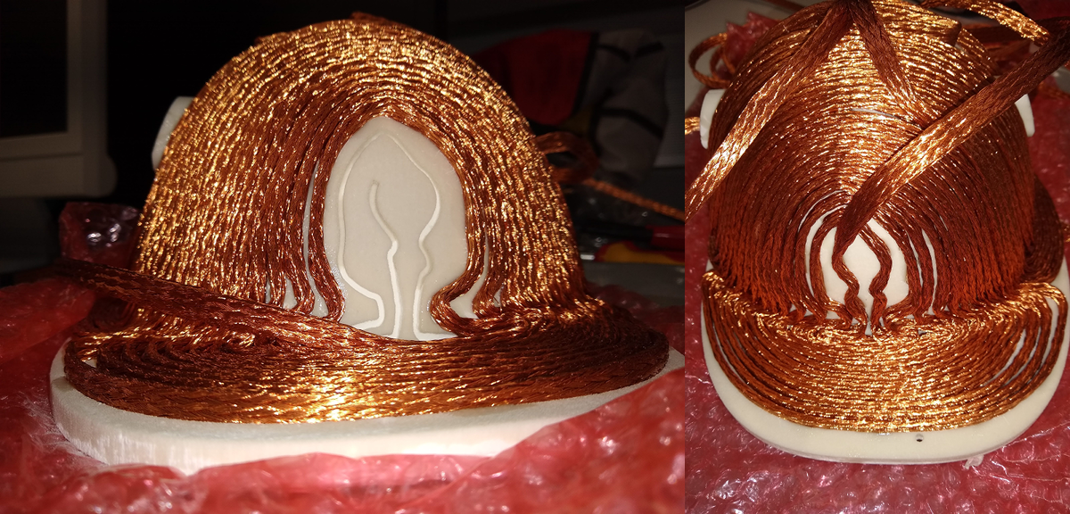
Figure 3: Coil carrier during winding of the coil:
Litz-wire was manually bent and pushed into the printed grooves. The final coil will be cast in epoxy resin under vacuum. Water cooling will be incorporated.
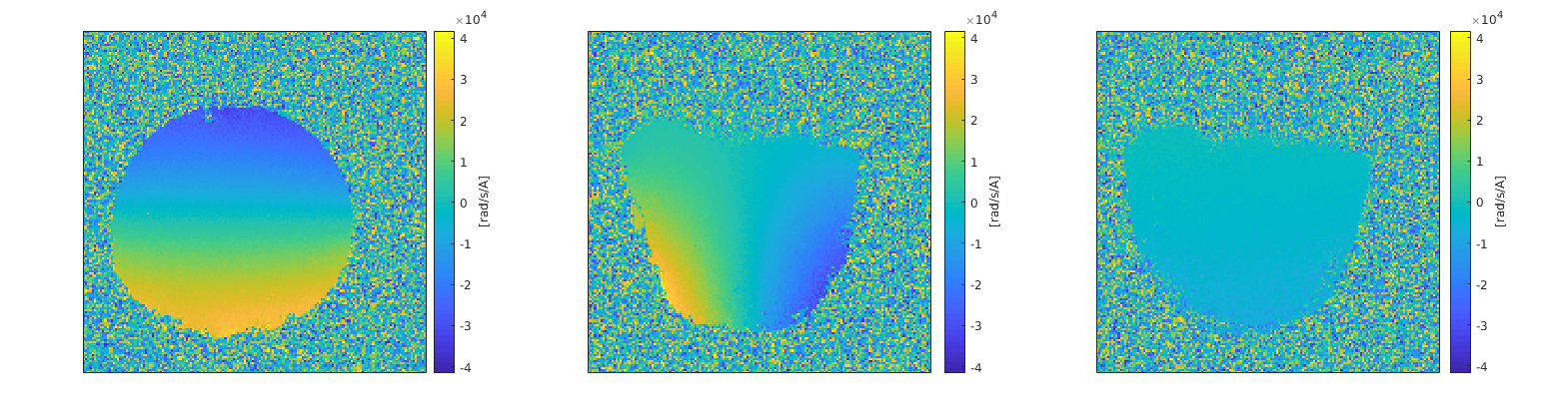
Figure 4: Measured phase difference maps:
Depicted are phase difference maps in the following orientations: a) (left) coronal, b) (center) saggital and c) (right) transversal. Due to measurements with the conventional whole-body RF coil for transmit and reception with a flexible 4 channel coil the received signal was very low. Therefore no masking was performed.
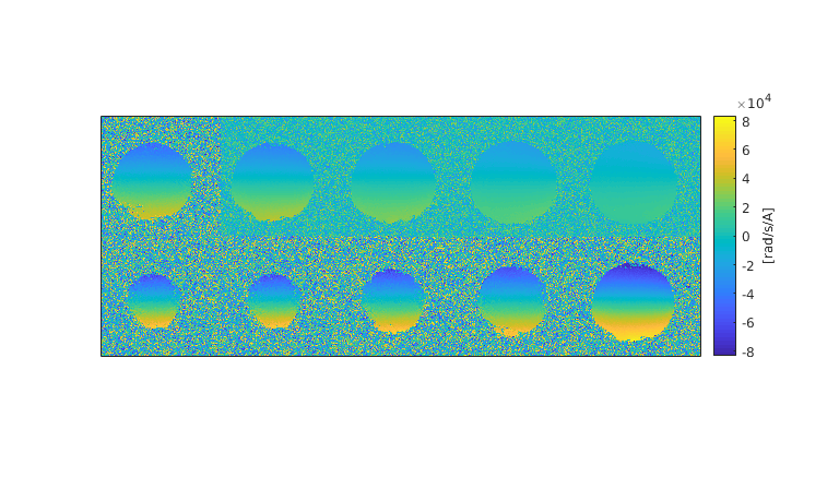
Figure 5: Coronal phase difference maps for multiple slices
Shown are coronal maps with a distance of 10 mm. The coil design was optimized for constant gradients in coronal orientation. In can be seen that the strongest gradients (= spatial derivative of the phase) occurs at the bottom of the cup and are reduced towards the top, where the chest wall will be located.