1126
Assembly of a PNS predicting “P-matrix” on a Huygens’ surface for rapid PNS assessment of 2D or 3D gradient coil windings1A.A. Martinos Center for Biomedical Imaging, Massachusetts General Hospital, Dept. of Radiology, Charlestown, MA, United States, 2Harvard Medical School, Boston, MA, United States, 3Computer Assisted Clinical Medicine, Medical Faculty Mannheim, Heidelberg University, Mannheim, Germany, 4Harvard-MIT Health Sciences and Technology, Cambridge, MA, United States
Synopsis
Peripheral Nerve Stimulation (PNS) modeling has a potential role for designing and operating therapeutic and diagnostic devices (such as MRI), but is computationally demanding due to the required simulations of EM fields and neural responses. We describe compression of the PNS modeling framework into a single versatile PNS matrix (P-matrix) defined on a Huygens’ surface just outside the subject’s body to allow fast detailed PNS analysis on arbitrary coil windings/formers. This P-matrix can be translated to any coil former within seconds, allowing for rapid PNS assessment or optimization of gradient coil windings with explicit PNS constraints.
Target audience
MR safety researchers, MRI gradient designers, MR engineersPurpose
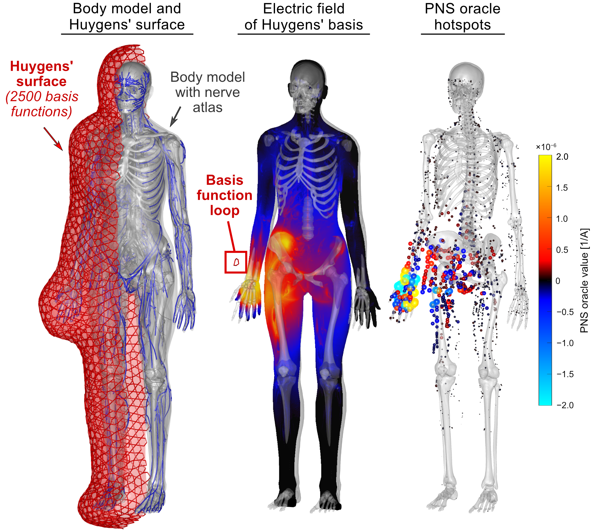
The ability to quickly assess Peripheral Nerve Stimulation (PNS) has the potential to become an important tool for optimizing MRI gradient coils as well as nerve stimulation devices. In both cases, the designer or device operator must quickly assess if and where a candidate coil or current pattern induces action potentials. We have recently demonstrated the precomputation of the PNS contributions of individual wire segments (or current density basis elements) into a matrix of linear PNS oracles (the “P-matrix”) [1,2,3]. This matrix (multiplied with the basis element weights) completely characterizes the PNS response and can be incorporated as a linear constraint in BEM-SF gradient winding optimization method [4,5,6]. Although powerful, this approach is very time-consuming in that it requires precomputation of the oracle P-matrix for the candidate winding former. Switching to a different winding former or moving the body model within the former requires re-computation of the P-matrix. Here, we propose a generalized P-matrix formulation which utilizes Huygens’ principle to allow a single P-matrix calculated on a close-fitting surface near the body to be applied in the design or assessment of windings on any surface exterior to the Huygens' surface. This generalizes the P-matrix approach to arbitrary coil geometries and body positions without the need to perform time-consuming E-field simulations.Methods
The intermediate surface mesh is designed to enclose the entire body model with a minimum distance between to the boundary of the body (e.g., 5 cm). We densely populate the Huygens’ surface with small current loops serving as basis functions for the electromagnetic fields. We have found that 2500 bases with a few millimeter in diameter is adequate for modeling typical gradient coils. We pre-compute two matrices for the set of Huygens’ bases:- We simulate the B-field components ($$$B_{x}$$$, $$$B_{y}$$$ and $$$B_{z}$$$) on target points equally distributed within the body model for every Huygens’ basis, yielding a matrix $$$B_{H}$$$ of size $$$3b\times n_{H}$$$ ($$$b$$$: number of target points, $$$n_{H}$$$: number of Huygens’ basis functions). The $$$B_{H}$$$ matrix can be simulated using the fast Biot-Savart formulation.
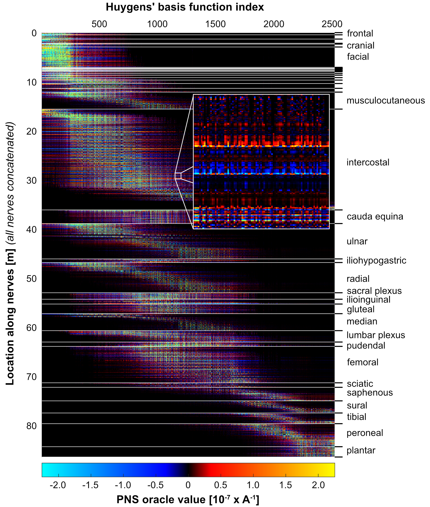
- We simulate the E-field that every Huygens’ basis induces in the body model, and extract the PNS oracle values [2] along all nerves of the body model. The combination of PNS oracles induced by all Huygens’ bases along all nerve segments yields the PNS matrix $$$P_{H}$$$ with size $$$p\times n_{H}$$$ ($$$p$$$: number of nerve segments in the body, $$$n_{H}$$$: number of Huygens’ basis functions). Note that the $$$P_{H}$$$-matrix is body model specific.
$$P_{D} = P_{H}M$$
Importantly, creating this mapping matrix $$$M$$$ only takes a few seconds since the same matrix maps the B-fields of the stream-function basis elements of the Huygens surface onto the design surface, i.e. $$$B_{H}M = B_{D}$$$. Thus, we can precompute $$$B_{H}$$$ and $$$B_{D}$$$ using Biot-Savart and solve for $$$M$$$ (we solve the system of equations in its normal form):
$$M = \text{argmin}_{M} \left\{\| B_{H}^{\text{T}}B_{H}M - B_{H}^{\text{T}}B_{D} \|\right\}$$
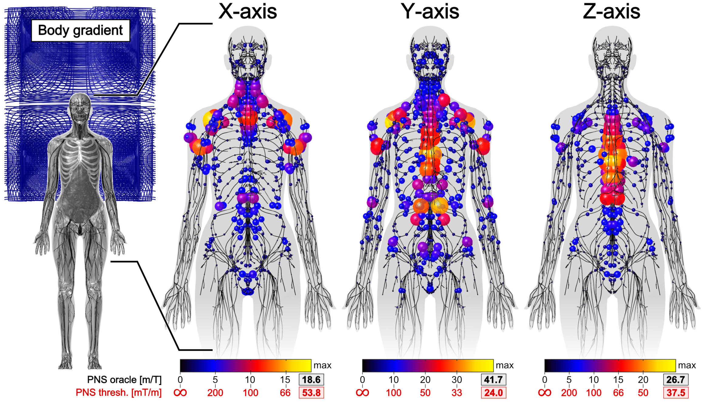
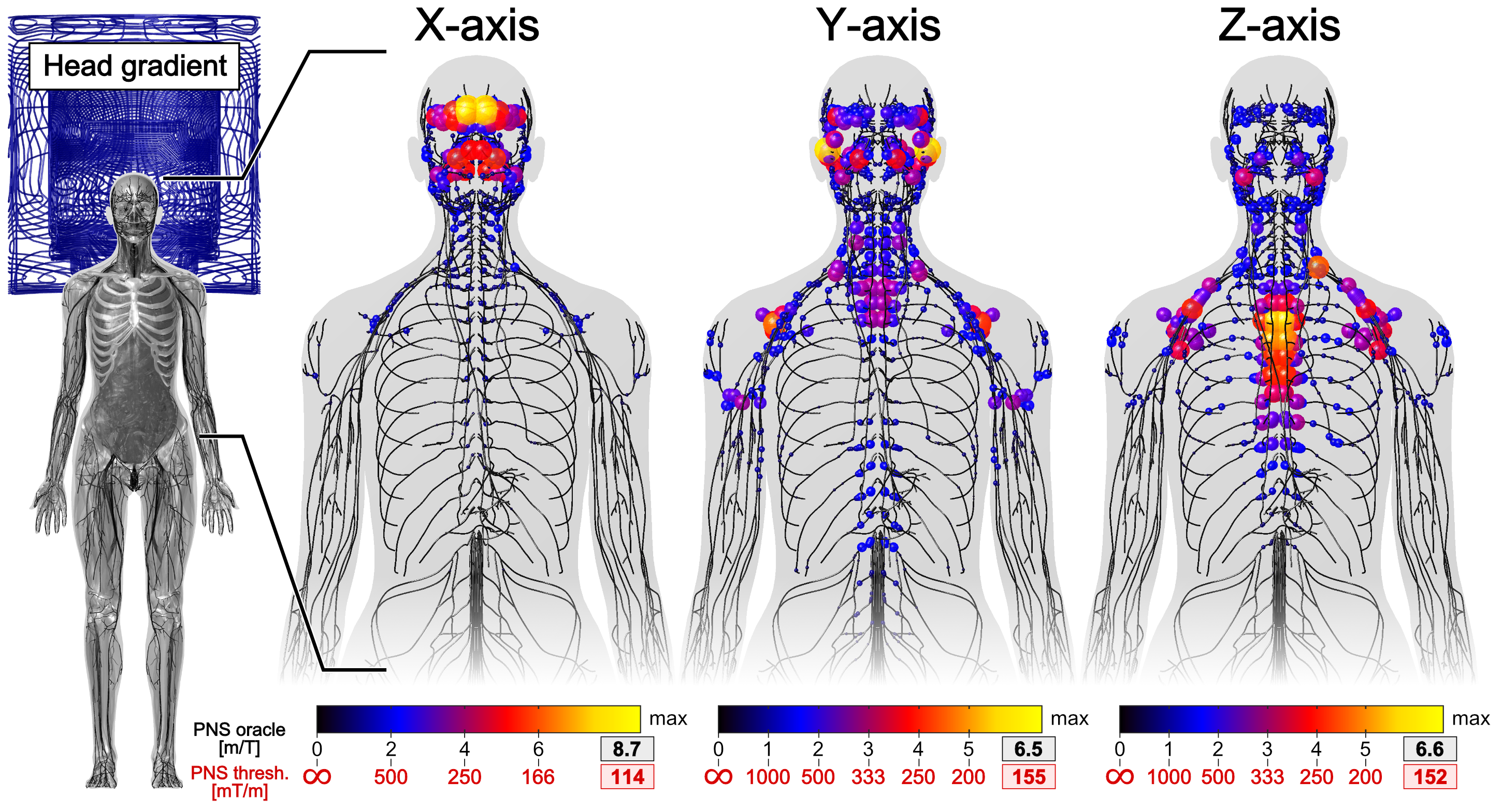
The Huygens’ P-matrix can also be used to predict PNS thresholds for discrete coil windings within seconds (where the sources are discrete wires, instead of stream functions). In this case, projection of the Huygens’ matrix is achieved using a mapping vector $$$m$$$ (rather than a matrix $$$M$$$, since the coil corresponds to a single basis element). The PNS threshold is given by the inverse of the maximum absolute PNS oracle, i.e., $$$\text{max}\{\ |P_H m|^{-1} \}$$$.
Results
Figure 2 shows the full Huygens’ P-matrix of our female body model (calculation time was 21 days). Figures 3 and 4 show PNS oracle maps for a whole body gradient and a head gradient generated using this P-matrix (runtime was 10 seconds per gradient axis). The maximum percentage PNS oracle deviation between the fast Huygens’ prediction (10 seconds per coil) and the full electromagnetic simulations (23 hours per coil) was <1% for the X/Y axes, and higher for the Z-axes of the head/body gradients (4% and 8%). These deviations can likely be reduced by including the free-space E-fields of the coil and the Huygens' bases (additionally to the B-fields) to optimize the Huygens' bases weights.Conclusion
The general P-matrix formed on a close-fitting Huygens’ surface provides a fast and simple workflow to assess PNS for gradient coils and incorporate PNS metrics into the standard approach for gradient winding optimization. Instead of recomputing PNS oracle matrices for different winding patterns or coil former shapes (which requires time-consuming E-field simulations), we map a precomputed Huygens’ P-matrix to the individual winding pattern or coil shape. This mapping can be performed quickly since it relies on fast Biot-Savart simulations. Thus the Huygens’ P-matrix formulation provides a versatile compressed representation of our PNS model that can be readily used for a large number of applications, such as design of PNS optimized gradients, online PNS monitoring on the MR scanner for different patient positions, and guided placement of magnetostimulation devices.Acknowledgements
Research was supported by the NIBIB of the National Institutes of Health under award numbers R00EB019482, U01EB025121, and U01EB025162. The content is solely the responsibility of the authors and does not represent the official views of the National Institutes of Health.References
[1] Davids et al., “Peripheral Nerve Stimulation (PNS) constrained gradient coil design within a Boundary Element Method Stream Function (BEM-SF) optimization”, ISMRM 2019
[2] Davids et al., “Optimizing selective stimulation of peripheral nerves with arrays of coils or surface electrodes using a linear peripheral nerve stimulation metric”, J Neural Eng, 2019
[3] Davids et al., “Prediction of peripheral nerve stimulation thresholds of MRI gradient coils using coupled electromagnetic and neurodynamic simulations”, MRM 81(1), 2019
[4] Peeren et al., “Stream function approach for determining optimal surface currents”. Journal of Computational Physics, 191(1), 2003
[5] Lemdiasov et al., “A stream function method for gradient coil design”, Concepts Magn. Reson., 26(1), 2005
[6] Poole et al., “Convex optimisation of gradient and shim coil winding patterns”. Journal of Magnetic Resonance, 2014.
Figures