1124
Surgical modification of extracranial trajectories of DBS leads can significantly reduce image artifact and RF heating during MRI at 3T1Northwestern University, Chicago, IL, United States, 2Northwestern Medicine, Chicago, IL, United States, 3Albany Medical Center, Albany, NY, United States
Synopsis
Patients with deep brain stimulation (DBS) implants can significantly benefit from MRI, however the interaction between MRI electric fields and DBS leads induces RF currents in the leads that can cause tissue heating and image artifacts. Here we show that modifying the extracranial trajectory of a DBS lead implanted into a cadaver brain significantly reduces both heating in the tissue and the image artifact around electrode contacts during MRI at 3T. Electromagnetic simulations confirm that trajectory modification can reduce induced currents in the lead, which in turn reduces the SAR amplification and distortion of B1 fields around the electrodes.
Introduction
Localization of individual deep brain stimulation (DBS) electrodes with submillimeter accuracy is crucial for successful device programming1. During MRI, electric currents are induced on DBS conductive leads in the transmit phase, causing both tissue heating and image artifact. Although tissue heating has been the subject of extensive research2-15, the image artifact due to distortion of B1 field due to induced RF currents has been less explored. In the case of long conductive wires, such RF induced artifact can dominate the susceptibility effect16-17 severely hindering electrode localization. In this work we applied numerical simulations to show that the B1 distortion is the dominant cause of image artifact during DBS MRI, and that its effect can be significantly reduced through surgical modification of trajectory of extracranial portion of the lead. Our experiments with a commercial DBS lead implanted in a human cadaveric brain undergoing MRI at 3T show that this technique can reduce image artifact around electrode contacts by up to 88%. As expected, the technique also reduced heating in the tissue by 95%.Methods
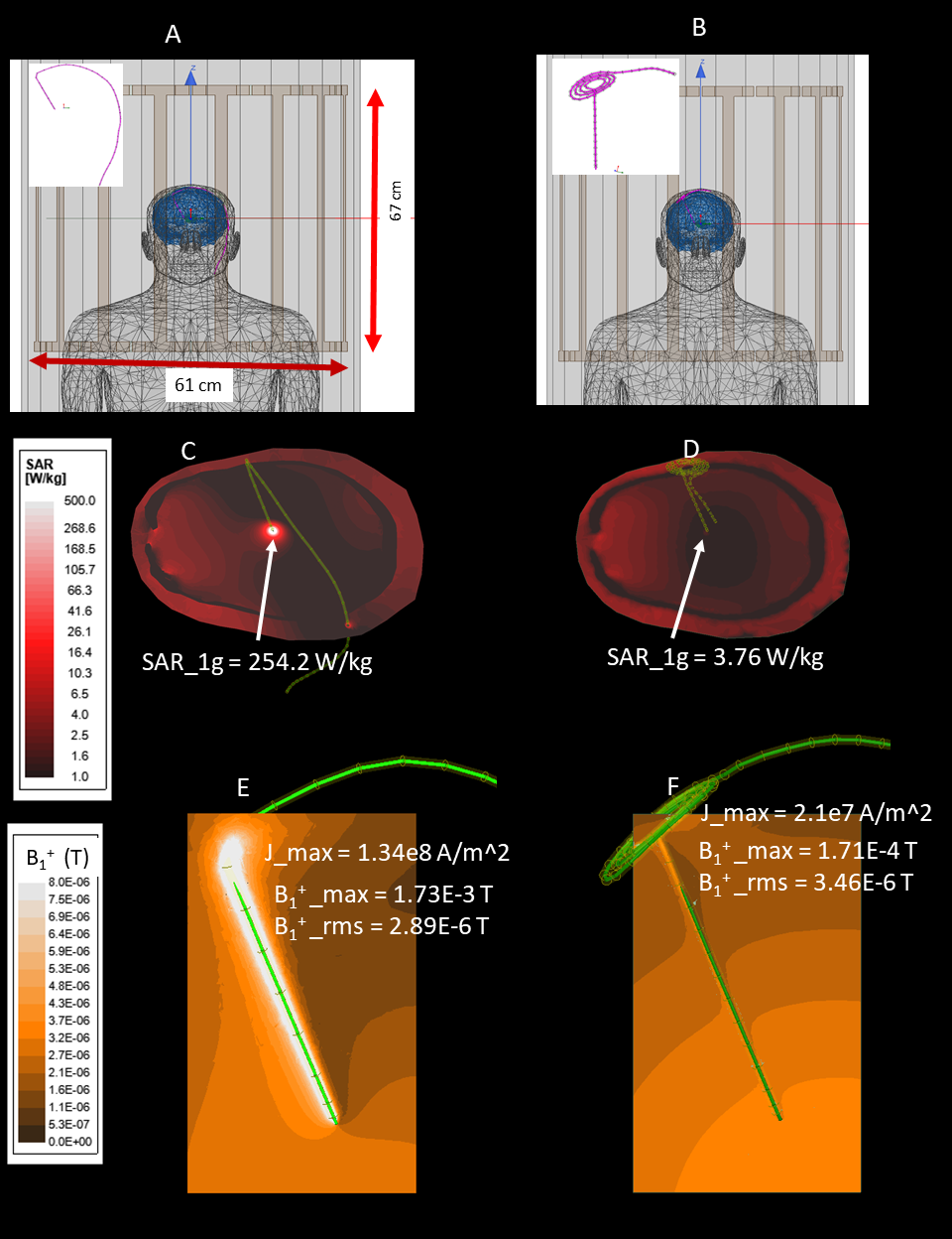
Electromagnetic simulationsWe quantified the local distortion of B1 field due to induced currents in a DBS lead with different extracranial trajectories. Electromagnetic simulations were performed in ANSYS Electronic Desktop 2019R1 (ANSYS, Canonsburg, PA) using a combined finite-element and circuit analysis method19. A 40-cm insulated wire with a 2mm exposed tip was positioned inside a body model consisting of brain (σ = 0.40 S/m,εr =78), skull (σ= 0 S/m,εr=3.5), and average tissue (σ = 0.48 S/m,εr =78). The tip of the wire was placed at a location analogous to the subthalamic nucleus (STN, DBS main target nuclei) and the entry point on the skull was selected based on typical STN DBS surgical approach. The extracranial portion of the lead was routed towards the neck following (1) a straight medio-lateral trajectory, and (2) a modified trajectory where three concentric loops were introduced at the surgical burr hole (Figure 1 A&B). The latter trajectory has recently been shown to reduce induced RF currents in the lead20,21. The model was placed in an RF coil tuned to 127 MHz with the head positioned at the iso-center. For each trajectory, we recorded the maximum of induced currents in the lead, the maximum of 1g-averaged SAR around the lead-tip, and the distortion in B1+ field quantified as maximum change in B1+ near the lead relative to the root-mean-square value of B1+ on a 4cm-diameter transverse plane 2cm below the lead-tip.
Experiments
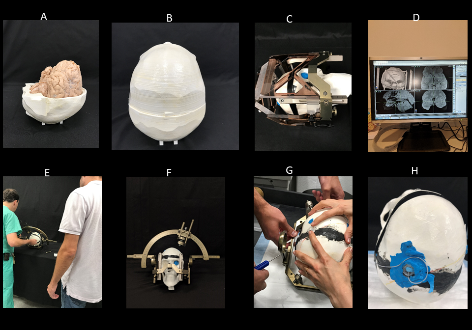
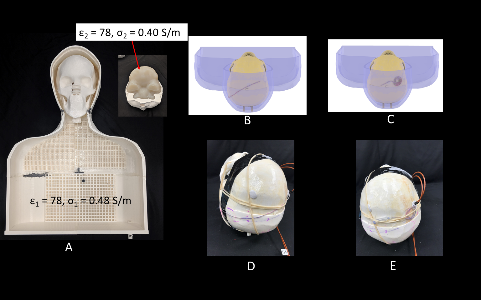
An anthropomorphic phantom was created consisting of a human-shaped container and a 3D printed skull based on imaging data. A cadaveric brain prepared and fixed in formalin was positioned inside the open skull before the two halves were glued together. A Leksell Coordinate Frame G (Elekta, Stockholm, Sweden) was secured to the skull and the system was scanned at 1.5T along with the MRI fiducial box. The images were transferred to BrainLab iPlan server to determine the target and entry point using combination of standard stereotaxy formula coordinates for subthalamic nucleus and direct visualization of MRI images. A Medtronic DBS lead (model 3387) was implanted into the subthalamic nucleus of the cadaver brain with the help of an stereotactic arc attached to the base ring and a DBS cannula inserted 10mm proximal to the target (Figure 2). The skull was then placed into the anthropomorphic container filled with saline (σ=0.48S/m,εr=78) and imaged in a Siemens 3T Prisma scanner with the extracranial portion of the lead routed along each of the two trajectories described above (Figure 3).
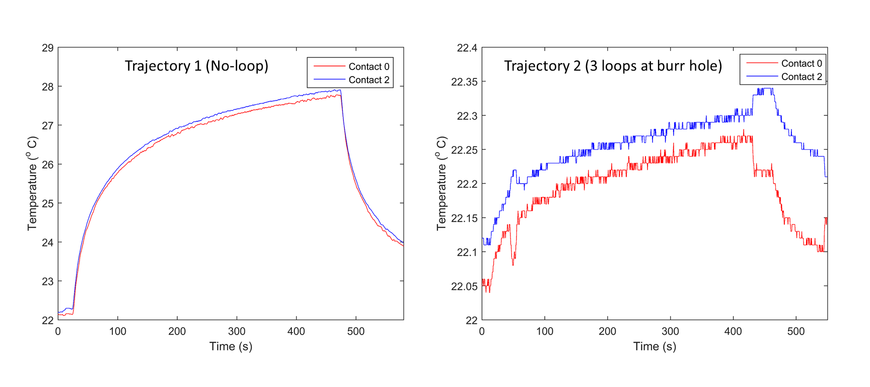
To measure RF heating, the 3D printed skull structure containing cadaveric brain was replaced with a skull structure filled with agar gel having electrical properties mimicking gray matter (σ=0.40S/m,εr =78). Temperature probes (OSENSA, Vancouver CA) were secured at tips of a Medtronic DBS lead (model 3387) and inserted into the skull. Temperature rise was measured during 7 minutes RF exposure for each trajectory (Figure 5). Details of imaging parameters are given in Figure 4.
Results
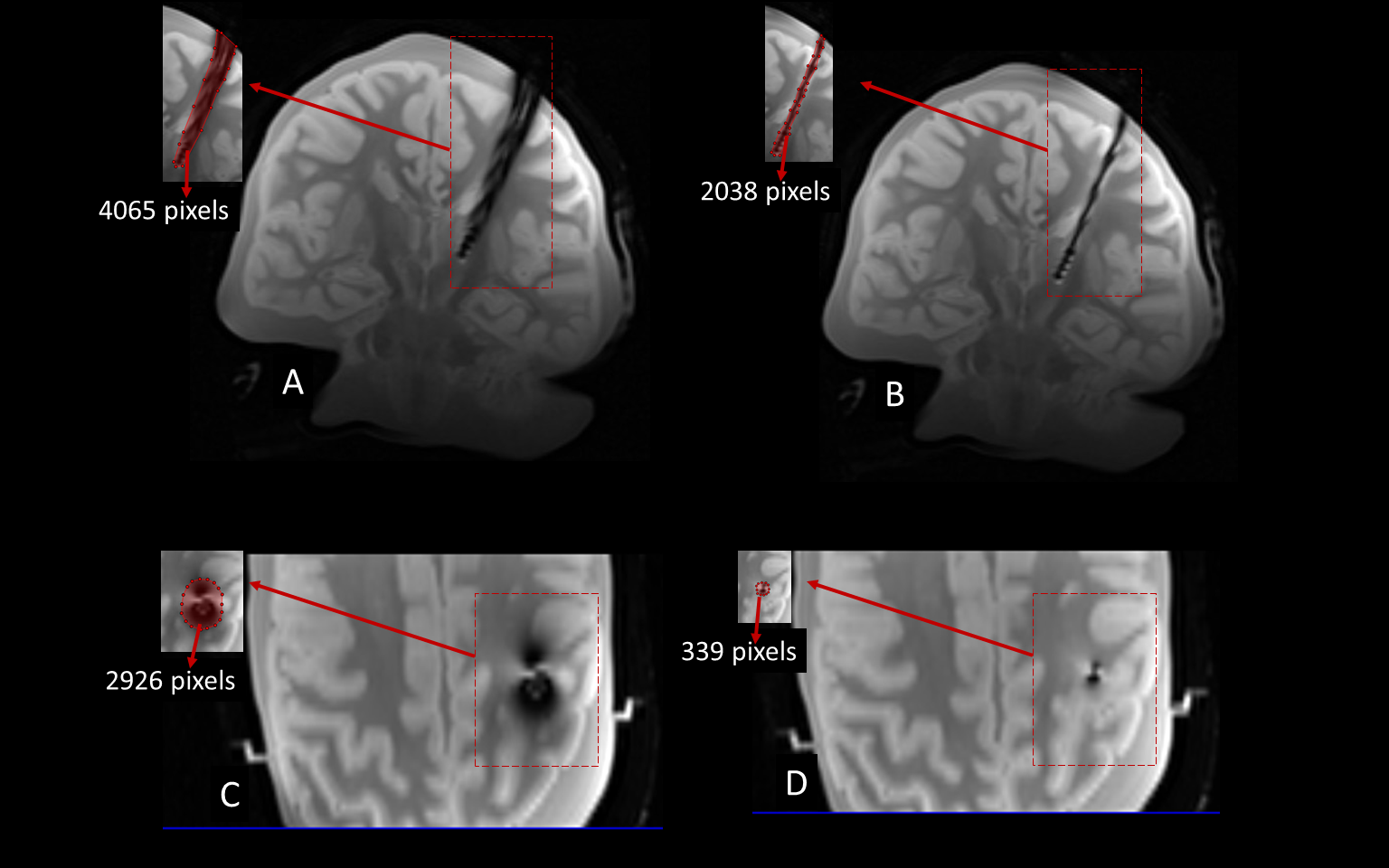
Numerical simulations showed that modifying the extracranial portion of the DBS lead reduced the induced currents in the lead by 84.3%, the maximum of 1g-SAR in the tissue by 98.5%, and the local B1+ distortion around the electrodes by 91%. Experimentally, the reduction in tissue SAR translated to 5.4 ˚C reduction in RF heating during 7 minutes of scanning. The reduction in B1+ distortion reduced the image artifact by 88.4% in a transverse plane and by 49.8% on a coronal plane passing through the electrode.Conclusions
Currently, surgical guidelines are completely silent as to how to best place the extracranial portion of DBS leads, leading to arbitrary (and highly variable) lead positioning by surgeons which can cause avoidable image artifact and tissue heating. Here we showed that simple modifications in the extracranial portion of DBS leads can significantly reduce both image artifact and tissue heating. These modifications can be implemented with minimal disruption to the surgical flow, thus dramatically shifting the risk-benefit ratio of applying MRI in these patients. We are currently working to implement trajectory modification in patients operated at two DBS centers in Northwestern University and Albany Medical Center.Acknowledgements
This work has been supported by NIH grants R00EB021320, R03EB025344, and R03EB024705.References
1. Horn, A. The impact of modern-day neuroimaging on the field of deep brain stimulation. J Curr Opin Neurol 32, 000-000 (2019).
2. McElcheran, C., Golestanirad, L., Iacono, M., Wei, P.-S., Yang, B., Anderson, K., . . . Graham, S. Numerical Simulations of Realistic Lead Trajectories and an Experimental Verification Support the Efficacy of Parallel Radiofrequency Transmission to Reduce Heating of Deep Brain Stimulation Implants during MRI. Nature Scientific Reports 9, 2124 (2019).
3. Bhusal B, Bhattacharyya P, Baig T, Jones S, Martens M. Measurements and simulation of RF heating of implanted stereo electroencephalography electrodes during MR scans. Magn Reson Med. 2018; 80: 1676– 1685.
4. Kazemivalipour, E., Keil, B., Vali, A., Rajan, S., Elahi, B., Atalar, E., . . . Golestanirad, L. Reconfigurable MRI technology for low-SAR imaging of deep brain stimulation at 3T: Application in bilateral leads, fully-implanted systems, and surgically modified lead trajectories. Neuroimage 199, 18-22 (2019).
5. Golestanirad, L., Lampman, D., Kazemivalipour, E., Habara, H., Atalar, E., Rosenow, J., . . . Kirsch, J. RF heating of deep brain stimulation implants in open-bore vertical MRI systems Magnetic resonance imaging InPress (2019).
6. Golestanirad, L., Kazemivalipour, E., Keil, B., Downs, S., Kirsch, J., Elahi, B., . . . Wald, L. L. Reconfigurable MRI coil technology can substantially reduce RF heating of deep brain stimulation implants: First in-vitro study of RF heating reduction in bilateral DBS leads at 1.5 T. PLoS One In Press (2019).
7. Golestanirad, L., Angelone, L. M., Kirsch, J., Downs, S., Keil, B., Bonmassar, G. & Wald, L. L. Reducing RF-Induced Heating Near Implanted Leads Through High-Dielectric Capacitive Bleeding of Current (CBLOC). IEEE Transactions on Microwave Theory and Techniques 67, 1265-1273 (2019).
8. Wei, P.-S., Yang, B., McElcheran, C., Golestanirad, L. & Graham, S. J. Reducing Radiofrequency-induced Heating in Realistic Deep Brain Stimulation Lead Trajectories using Parallel Transmission. Proc. Int. Soc. Magn. Reson. Med. 26 (2018).
9. McElcheran, C. E., Yang, B., Anderson, K. J., Golestanirad, L. & Graham, S. J. Parallel radiofrequency transmission at 3 tesla to improve safety in bilateral implanted wires in a heterogeneous model. Magnetic resonance in medicine 78, 2406-2415 (2017).
10. McElcheran, C., Golestanirad, L., Iacono, M., Yang, B., Anderson, K., Bonmassar, G. & Graham, S. J. Low Heating B1 Mapping in Parallel Transmit for Deep Brain Stimulators. Proc. Intl. Soc. Mag. Reson. Med. 25 (2017).
11. McElcheran, C., Golestanirad, L., Iacono, M., Yang, B., Anderson, K., Bonmassar, G. & Graham, S. Parallel Transmission for Heating Reduction in Realistic Deep Brain Stimulation Lead Trajectories. Proc. Intl. Soc. Mag. Reson. Med. 25 (2017).
12. Golestanirad, L., Pilitsis, J., Martin, A., Larson, P., Keil, B., Bonmassar, G. & Wald, L. L. Variation of RF heating around deep brain stimulation leads during 3.0 T MRI in fourteen patient-derived realistic lead models: The role of extracranial lead management. Proc. Intl. Soc. Mag. Reson. Med. 25 (2017).
13. Golestanirad, L., Keil, B., Angelone, L. M., Bonmassar, G., Mareyam, A. & Wald, L. L. Feasibility of using linearly polarized rotating birdcage transmitters and close‐fitting receive arrays in MRI to reduce SAR in the vicinity of deep brain simulation implants. Magnetic resonance in medicine 77, 1701-1712 (2017).
14. Golestanirad, L., Iacono, M. I., Keil, B., Angelone, L. M., Bonmassar, G., Fox, M. D., . . . Mareyam, A. Construction and modeling of a reconfigurable MRI coil for lowering SAR in patients with deep brain stimulation implants. Neuroimage 147, 577-588 (2017).
15. McElcheran C, L. Golestanirad, and S. Graham, "Reduced Heating of Implanted Electrical Conductors Using Parallel Radiofrequency Transmission," Proc. Intl. Soc. Mag. Reson. Med. 22 2014.
16. Camacho, C. R., Plewes, D. B. & Henkelman, R. M. Nonsusceptibility artifacts due to metallic objects in MR imaging. Journal of Magnetic Resonance Imaging 5, 75-88 (1995).
17. Graf, H., Steidle, G., Martirosian, P., Lauer, U. A. & Schick, F. Effects on MRI due to altered rf polarization near conductive implants or instruments. Medical physics 33, 124-127 (2006).
18. Vashaee, S., Goora, F., Britton, M., Newling, B. & Balcom, B. Mapping B1-induced eddy current effects near metallic structures in MR images: A comparison of simulation and experiment. Journal of Magnetic Resonance 250, 17-24 (2015).
19. Golestanirad, L., Rahsepar, A. A., Kirsch, J. E., Suwa, K., Collins, J. C., Angelone, L. M., . . . Wald, L. L. Changes in the specific absorption rate (SAR) of radiofrequency energy in patients with retained cardiac leads during MRI at 1.5 T and 3T. Magnetic resonance in medicine 81, 653-669 (2019).
20. Golestanirad, L., Kirsch, J., Bonmassar, G., Downs, S., Elahi, B., Martin, A., . . . Wald, L. L. RF-induced heating in tissue near bilateral DBS implants during MRI at 1.5 T and 3T: The role of surgical lead management. NeuroImage 184, 566-576 (2019).
21. Golestanirad, L., Angelone, L. M., Iacono, M. I., Katnani, H., Wald, L. L. & Bonmassar, G. Local SAR near deep brain stimulation (DBS) electrodes at 64 MHz and 127 MHz: A simulation study of the effect of extracranial loops Magnetic Resonance in Medicine 88, 1558-1565 (2016).
Figures