1123
Convex Optimized Excitation Control to Reduce RF Heating for DBS Patients at UHF MRI1Biomedical Engineering, Hanyang University, Seoul, Republic of Korea
Synopsis
Patients having deep brain stimulation (DBS) can suffer from radio-frequency (RF) heating around the electrode during the MRI scan. Most of previous solutions were conducted based on the birdcage coil; the methods are inappropriate for ultra-high field (UHF) MRI system over 7 T using multi-channel RF coil. Our study introduced an optimized excitation control method by changing input weights of coil elements through convex optimization. Results demonstrated that proposed method effectively reduces RF heating around the electrode as well as acquires MR images of major brain regions with high resolution simultaneously.
Introduction
During MRI scan, metallic components of IMD have high conductivity that there is a potential to induce extremely high specific absorption rate (SAR) and hazardous heating by eddy currents around the device. Especially, the conductor shape of the lead wire acts as an antenna that patients who have an inserted device using lead wire such as deep brain stimulator (DBS) are concerned as the worst heating case. Even though some solutions are introduced to alleviate the heating around DBS electrode, previous methods are implemented based on the birdcage coil [1-3]; which is inappropriate for ultra-high field (UHF) MRI using multi-channel RF coil. In this study, we numerically analyzed the RF heating of DBS patients exposed to UHF MRI through finite difference time domain (FDTD) method [4]. Because inhomogeneous B1+ field induces an electric field to increase SAR, amplitude and phase of each channel was modified to apply strong and homogeneous B1+ field around the electrode by convex optimization. The results showed the proposed method is useful to alleviate the biological heating effect around the DBS electrode exposed to the UHF MRI system and achieve the high-resolution MR images of the major brain regions at the center of the head simultaneously.Methods
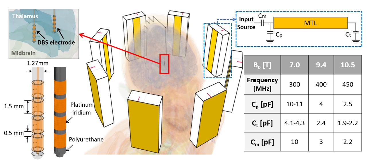
To focus B1+ field at the center of the head, a convex optimization to control amplitude and phase of each element was used to calculate optimized weights applicable for the head shape [5]. thermal and EM results near the electrode using convex optimized input (ωc) were estimated and compared with the cases with uncontrolled input (ωu) and phase-modified input (ωp). For the comparison, electromagnetic field, SAR, and temperature rising around DBS electrode in the human head were calculated at 7, 9.4 and 10.5 T. Figure 1 shows the simulation setup for this study. The lead was modeled based on a commercial product (lead model 3389: Medtronic Inc. Minneapolis, MN, USA), and electrode were inserted at the bottom of the thalamus. For the multi-channel RF coil design, a transverse electromagnetic (TEM) coil was used for the simulation [6]. To match the coil element at the mentioned frequencies, three capacitors (Cp, Ct and Cm) were used to achieve the source impedance matching at 50 Ω that the capacitance ranges for the optimum resonance are listed in the table at the lower right inset of Figure 1. To evaluate the effect of the number of leads, numerical scenarios including single and dual DBS system were estimated individually.Results
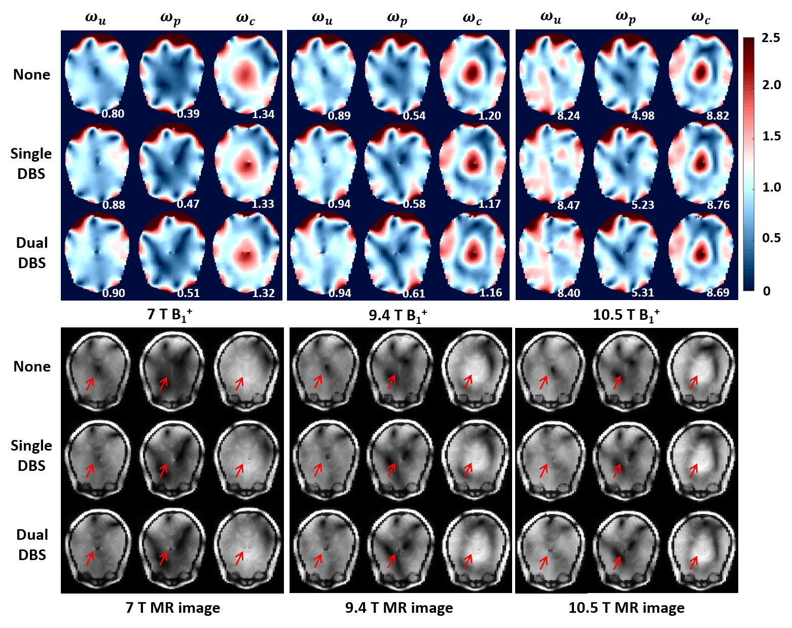
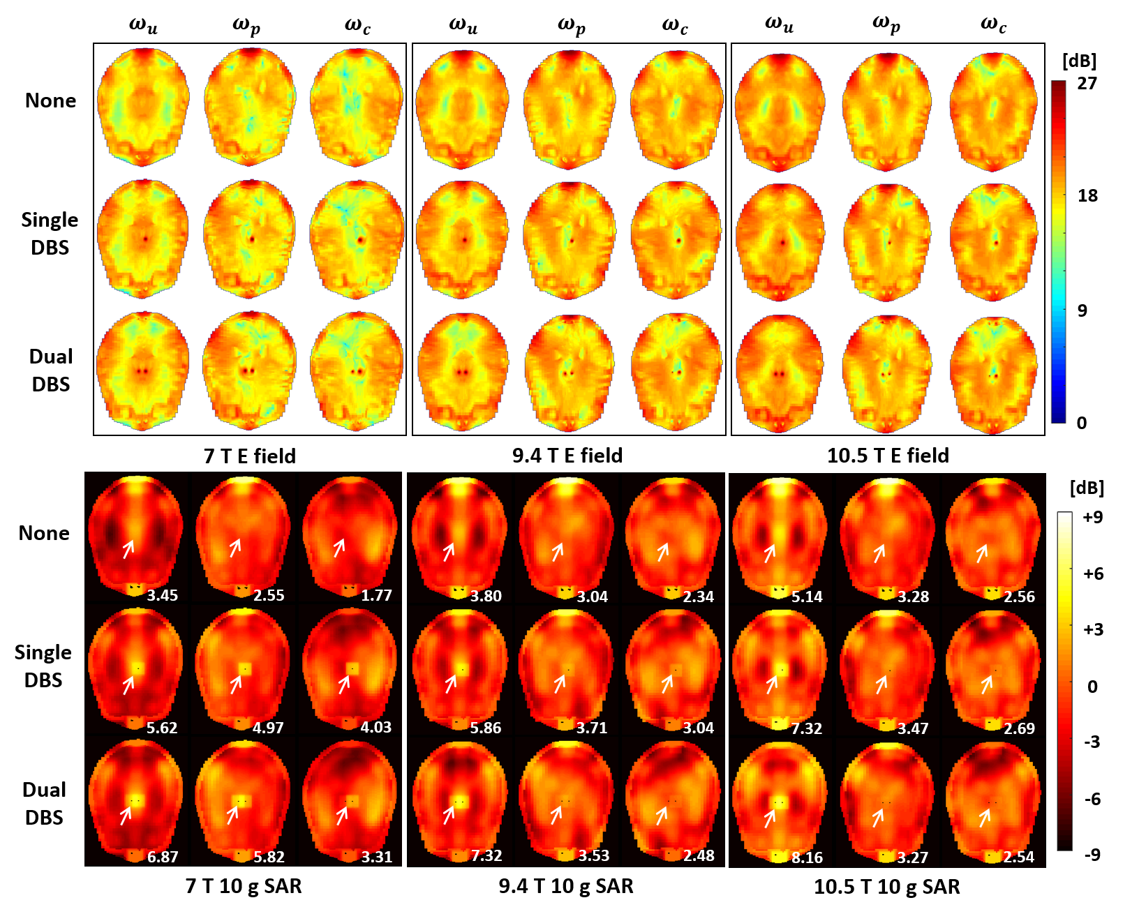
The ωc (amplitude and phase) series calculated by convex optimization were depicted in figure 2. The series were distinguished by the shape of the line; solid, dashed, and dotted line are plotted for the weights at 7,9.4, and 10.5 T, respectively. Figure 3 shows the B1+ fields and the MR images provided by the RF coil with the different weights. Mean of B1+ field applied at the center of the head of each scenario was individually presented at the lower right corner. The total power of the coil for all cases were normalized to such that the mean of the B1+ on the axial slice was 2 µT for the comparison. MR images obtained numerically through the Bloch equation that a GRE sequence was used to acquire transverse T1-weighted images (FOV = 240 mm × 240 mm, FE × PE = 128 x 128, TR = 500 ms, TE = 3 ms, Flip angle = 15◦, Bandwidth = 50 kHz, slice thickness = 3 mm). According to the figure, B1+ field with the highest intensity among three input cases was observed at the center of the head when the ωc was used as the input. Also, regardless of the B0 and the number of the DBS, well-fined MR images over the whole head were commonly obtained by using the ωc. Figure 4 shows the electric field and SAR10g on the axial slice of exposed by the UHF MRI systems depending on the control methods. For the comparison, the electric field of 1 V/m and theSAR10g of 2 W/kg were normalized to 0 dB, respectively. Also, a peak of the SAR10g plot around the center of the head was individually presented at the lower right corner. By using ωp or ωc , the inhomogeneity of the overall electric field was alleviated, and lower peak SAR10g in the ROI, especially about 70 % decrease by using ωc for dual DBS at the 10.5 T, was obtained.Conclusion
In this study, RF heating around DBS electrode exposed at UHF MRI at 7, 9.4, 10.5 T was numerically estimated. In addition, a proper control method of multi-channel RF coil was introduced. By acquiring the input weights of the coil elements through the convex optimization to focus B1+ field at the center of the head, both the alleviation of the biological heating effect around the DBS electrode and the high-resolution MR images of the major brain regions at the center of the head were efficiently achieved simultaneously. The results show that the proposed method will be useful for the clinical field in the near future when the UHF MRI and DBS system are widely used.Acknowledgements
This work was supported by the Basic Science Research Program through the National Research Foundation of Korea funded by the Ministry of Science and ICT under Grant 2019R1A2C2004774.References
[1] Guérin B, Gebhardt M, Serano P, Adalsteinsson E, Hamm M, Pfeuffer J, et al. Comparison of simulated parallel transmitbody arrays at 3 T using excitation uniformity, global SAR, local SAR, and power efficiency metrics. Magn Reson Med 2015;73:1137–1150.
[2] Golenstanirad L, Boris K, Angelone LM, Bonmassar G, Mareyam A, Wald LL. Feasibility of Using Linearly Polarized Rotating Birdcage Transmitters and Close-Fitting Receive Arrays in MRI to Reduce SAR in the Vicinity of Deep Brain Simulation Implants. Magn Reson Med 2017;77:1701–1712.
[3] Golestanirad L, Angelone LM, Iacono MI, Katnani H, Wald LL, Bonmassar G. Local SAR near deep brain stimulation (DBS) electrodes at 64 and 127 MHz: A simulation study of the effect of extracranial loops. Magn Reson Med 2017;78:1558–1565.
[4] Sim4Life by ZMT, https://www.zmt.swiss.
[5] Yoo H, Gopinath A, Vaughan JT. A method to localize RF fields in high-fields magnetic resonance imaging systems. IEEETrans Biomed Eng 2012;59:3365–3371
[6] Adriany G, de Moortele PFV, Wiesinger F, Moeller S, Strupp JP, Andersen P, et al. Transmit and receive transmission line arrays for 7 Tesla parallel imaging. Magn Reson Med 2005;53:434–445.
Figures