0768
Design and demonstration of an artificial dielectric for 7 T MRI1Department of Nanophotonics and Metamaterials, ITMO University, Saint Petersburg, Russian Federation, 2Department of Radiology, C.J.Gorter Center for High Field MRI, Leiden University Medical Center, Leiden, Netherlands, 3Department of Physics, Universidad Nacional de Colombia, Bogota, Colombia, 4School of Exact Sciences and Engineering, Universidad Sergio Arboleda, Bogota, Colombia, 5Aix Marseille University, CNRS, Centrale Marseille, Institut Fresnel, Marseille, France, 6Stevens Research Center, Carle Foundation Hospital, Urbana, IL, United States
Synopsis
We present a new approach replacing high-permittivity water-based dielectric pads with a non-resonant low-cost artificial dielectric to improve MR image quality by modifying the interferences present in the radiofrequency field at 7T MRI. The artificial dielectric comprises a stack of metal patches printed on dielectric substrates. Numerical studies and imaging of a head-phantom with the proposed structure showed the same increase in the transmit radiofrequency field distribution at the area of interest as for conventional dielectric pads. The advantages of the new structure include ease of manufacture and long-term stability.
Introduction
Ultra-high field MRI enables substantially improving the signal-to-noise ratio, contrast-to-noise ratio, angiographic capabilities and spectroscopic resolution in comparison to clinical (1.5 and 3 T) scanners. However, as the radiofrequency (RF) wavelength in the sample becomes comparable with its dimensions, the transmit field becomes distorted with sample-specific regions of higher- and lower-transmit field. Thus, image quality and diagnostic value can severely degrade. High-permittivity dielectric pads1, which consist of mixed ceramic powders and deionised water, have been shown to increase the magnetic field in regions of low transmit efficiency at high and ultra-high magnetic fields. Nevertheless, dielectric pads have some drawbacks: their material parameters can change with time, the materials they contain are not all biocompatible and can be quite lossy2. Here, we describe and demonstrate experimentally a new approach using a solid artificial dielectric instead of conventional ceramic-containing mixtures to modify the interferences present in the RF field at 7T.Methods
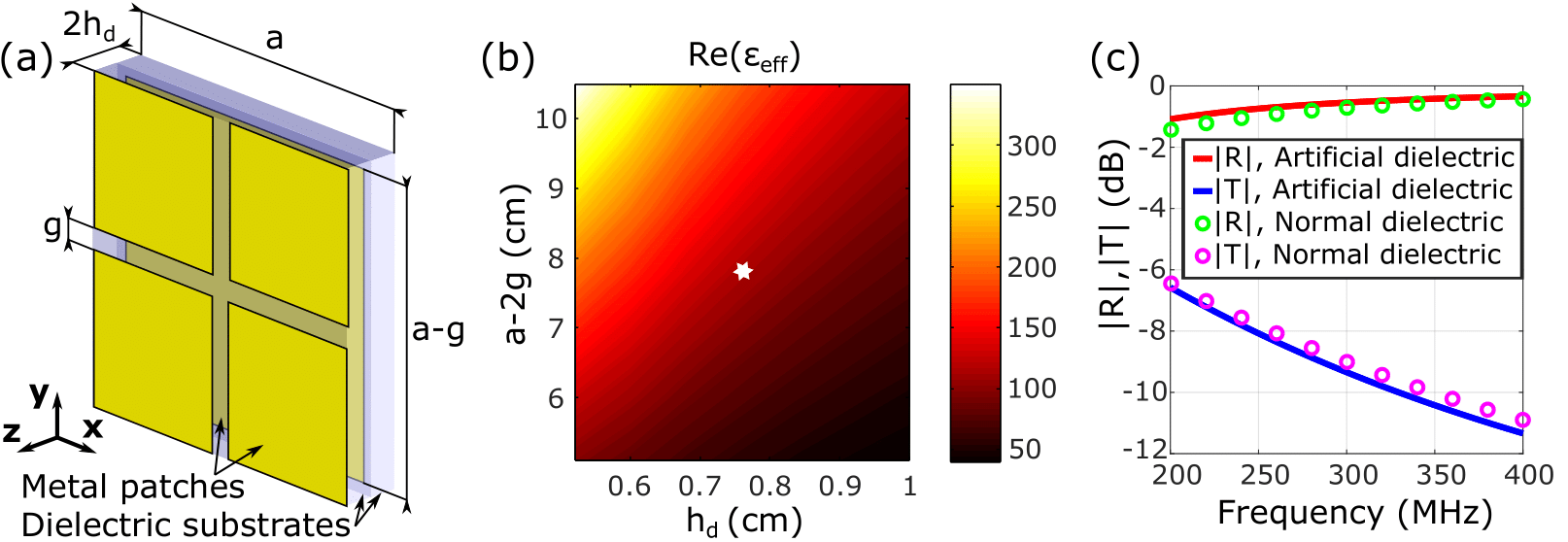
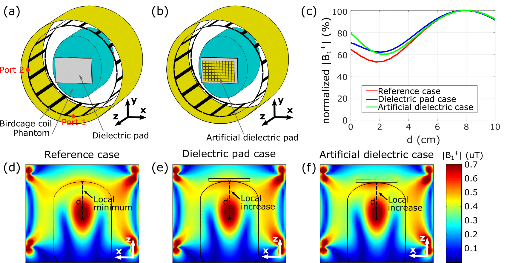
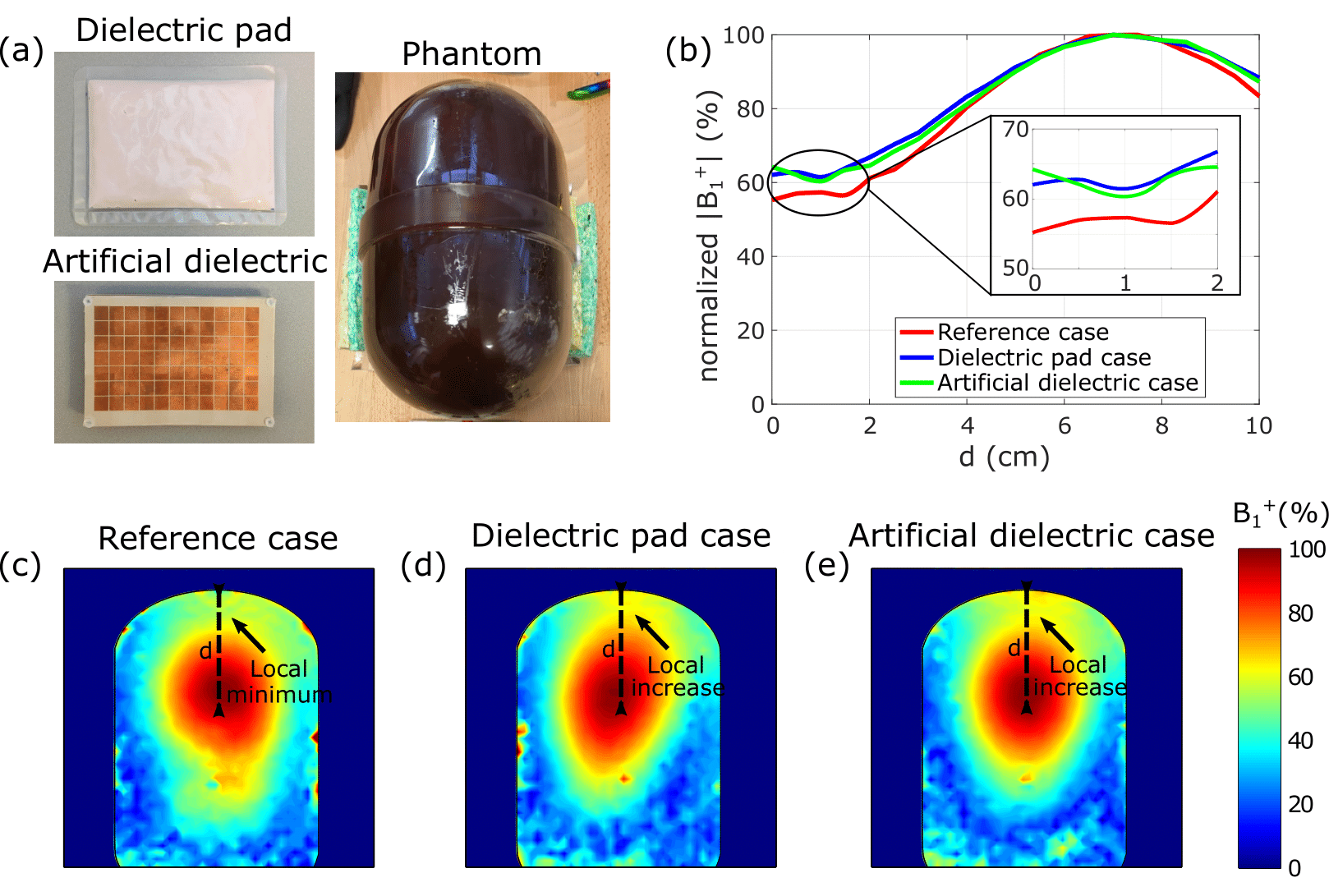
The artificial dielectric design was composed of stacked single layer printed circular boards with an etched periodic structure of small square metal patches. The unit cell geometry is demonstrated in Figure 1a with the following parameters: a=0.9 cm, g=0.06 cm, hm=0.0035 cm, hd=0.076 cm, a relative permittivity of the substrate ɛ=3.5 and its loss tangent tan δ=0.0013 (Arlon 25N). The dimensions of the artificial dielectric are chosen to produce a structure with the same properties as a conventional dielectric material. Accordingly, the artificial dielectric structure was modelled analytically by the homogenization approach and the following equation3: $$$ɛ_{eff}=\left(\frac{a/2-g}{h_{d}}\right)^2$$$. All numerical simulations were performed in CST Microwave Studio 2017. The artificial dielectric layer was considered as infinite in the plane of the structure and had a thickness of 7.95 mm (5-unit cells) to calculate the reflection (R) and transmission (T) coefficients. The material parameters of the artificial dielectric were extracted using the Nicolson-Ross-Weir method4. The Time Domain Solver was used to simulate the B1+ field distribution in a 7T birdcage coil containing a head-mimicking phantom5. The coil parameters correspond to 7T standard Tx birdcage coil (coil inner diameter Dinside=29 cm, shield diameter Dshield=33 cm, coil length lcoil=18 cm). The size of the entire metallization in the XY-plane of the artificial dielectric was 11.3×7.7 cm2. The dielectric pad used for comparison had the same geometric dimensions. We considered three cases illustrated in Figure 2 (numerical study) and Figure 3 (experiment): (1) a birdcage coil with the phantom (reference case); (2) the dielectric pad was placed adjacent to the phantom and (3) the artificial dielectric was placed in the same position as the dielectric pad. The artificial dielectric pad and phantom used in the experiment are shown in Figure 3a. Experimental results were acquired on a Philips Achieva 7T whole-body MRI scanner. B1+ maps were acquired using a DREAM sequence with acquisition parameters: voxel size = 5×5×5 mm3, flip angle = 10°, STEAM angle = 50°, TE/TR = 1.975/15 ms.Results
Figure 1b shows the numerically calculated dependence of the artificial dielectric’s effective permittivity (ɛeff) on the geometry. It is possible to achieve the desired relative permittivity value by tailoring the geometry. Figure 1c confirms that the artificial dielectric has the same reflection and transmission coefficients for a normally-incident plane wave as those of the dielectric of the same thickness (7.95 mm) with ɛ ~120 and tanδ~0.05. Figures 2d-f demonstrate the simulated B1+ field distribution in the XZ plane through the centre of the phantom for reference case, dielectric pad and artificial dielectric. We observe an increase in the field amplitude in the area marked by the black arrow in the presence of either the dielectric pad or artificial dielectric. Figure 2c compares B1+ field profiles taken from the 2D maps along the dashed black lines: both the conventional and artificial dielectrics gave ~10% B1+ field improvement. Figures 3b-e show measured B1+ field enhancement that confirms the simulation results.Discussion and conclusions
An artificial dielectric has been designed for improvement of transmit field distribution of a head coil for MRI 7T: this improvement would be useful for imaging the parietal lobes in vivo. The solid nature and ease of construction are among the advantages of the proposed structure, while its effect on the RF field is the same as for the conventional dielectric pad. It is important to note that usually the dielectric pads are placed parallel to the axis of the birdcage coil, rather than perpendicular. This is because such a position enhances the effect of the pad, and in this configuration is particularly useful in the temporal lobes, for example. However, the excitation produced by the birdcage is not appropriate for the artificial dielectric in this orientation. Indeed, far off the axis of the birdcage, the active direction of local plane-wave propagation turns is parallel to the artificial dielectric. In this case, the structure does not produce the same polarisation effect as a dielectric pad due to spatial dispersion (i.e. the strong dependence of the effective relative permittivity on the incidence angle).6 In order to extend the work presented here to a more general case, further development of the artificial structure that is invariant in terms of effective relative permittivity to the incidence angle is ongoing.Acknowledgements
This work was supported by the Russian Science Foundation (Grant No. 18-79-10167), by the European Union Horizon 2020 research and innovation programme under the grant agreement No. 736937 and by Horizon 2020 ERC Advanced NOMA-MRI 670629. ASh acknowledges funding support from the ISMRM RExGP. SG acknowledges the support of the President of the Russian Federation (МК-3620.2019.8). The authors thank Dr. ir. Wyger Brink and Mr Thomas Ruytenberg for assistance with dielectric pad and artificial dielectric slab fabrication.References
1. Teeuwisse WM et al. Simulations of high permittivity materials for 7 T neuroimaging and evaluation of a new barium titanate-based dielectric. Magn Reson Med. 2012;67(4): 912-918
2. Neves AL, et al. Compressed perovskite aqueous mixtures near their phase transitions show very high permittivities: New prospects for high-field MRI dielectric shimming. Magn Reson Med. 2018;79(3): 1753-1765
3. del Risco JP et al. Extremely thin Fabry-Perot resonators based on high permittivity artificial dielectric. 2016 10th Inter. Con. on Adv. Electromagnetic Mat. in Microwaves and Opt. Chania. 2016;40-42.
4. Luukkonen O, et al. A Stepwise Nicolson–Ross–Weir-Based Material Parameter Extraction Method. IEEE Ant. and Wireless Prop. Let.. 2011;10:1295-1298
5. Brink WM, et al. A simple head-sized phantom for realistic static and radiofrequency characterization at high fields. Magn Reson Med. 2018;80(4): 1738-1745
6. Belov PA, et al. Strong spatial dispersion in wire media in the very large wavelength limit. Phys. Rev. B 2003; 67: 113103
Figures