0764
A 64-Channel 7T array coil for accelerated brain MRI1Athinoula A. Martinos Center for Biomedical Imaging, Massachusetts General Hospital, Charlestown, MA, United States, 2Harvard Medical School, Boston, MA, United States, 3Siemens Medical Solutions USA, Boston, MA, United States
Synopsis
We construct and test a prototype 64-channel brain array coil for 7T and compare it to a 32-channel coil of similar design. Coil characteristics like signal to noise ratio, noise correlation matrix, and noise amplification (G-factor) for parallel imaging are described as well as and a comparison of the B1+ maps to assess birdcage coil efficiency and homogeneity. The coil was designed on a split-half former with a sliding top half to facilitate patient entry and utilizes a sliding birdcage coil for transmit
Introduction
Increasing the number of receive elements above 32 has been shown to provide improved accelerated brain imaging and modest peripheral SNR increases for non-accelerated imaging at 3T [1] and at 7T [2]. The principle pitfall of high channel count coils is the maintenance of body noise dominance as the individual coils become smaller. Ultrahigh field strength is well suited for utilizing the highest channel-counts possible since the degree of body loading increases with field strength as does parallel imaging performance [3]. With 64 receive channels recently available on an FDA cleared 7T device we sought to exploit this benefit and demonstrate the potential of the 64 channel system for brain imaging. Our prototype 64-channel receive array uses a split-former contoured to the head, a sparse wire layout [4] to reduce internal losses, integrated preamps placed a few centimeters off the former surface and a high-power transmit birdcage coil. The SNR and g-factors of the receiver array and the B1+ map of the transmit birdcage coil are compared with our 32-channel receiver array. The constructed coil was designed for routine use in a way that addresses patient comfort.Methods
The helmet former is shown in Fig. 1b. The helmet was sized to accommodate a majority of adult heads and is contoured at both the sides and the nape of the neck. The volume coil and top half of the receive array slide (in the bore direction) as shown in Fig. 1c to increase accessibility for the patient. Fig. 1a shows the receive array which has 24 elements on the top half (with a diameter of 5.5 cm) and 40 on the bottom half (with a diameter of 6 cm). Each loop is made of 16 AWG wire with four or five evenly-spaced capacitors. All elements are tuned to 297.2 MHz and matched when loaded to an impedance of 75 Ω to minimize the noise figure of the Siemens 7T preamplifiers. Preamplifier decoupling is achieved with a cable length of 6 cm. Placing the preamps near the coil elements yields a substantial reduction in cable losses but places them far enough away to reduce eddy current losses in the preamplifier itself. The active detuning circuit is formed across the match capacitor using an inductor and PIN diode.The transmit coil is a detunable 16-rung band pass birdcage with a rung length of 24cm. The birdcage conductors are routed using a 0.031” circuit board and then bent and fastened to the inside surface of a 33cm dia. fiberglass tube. This is nested inside a copper-clad kapton (polyamide) slotted shield which is epoxied to the inner surface of a 38cm dia. fiber glass tube The birdcage is tuned to 297.2 MHz with a series capacitance matched to a loaded impedance of 50 Ω. Tuned cable traps are used at the quadrature drive points at the top back side of the coil. PIN diodes are added to each rung and DC bias is delivered using circuit boards with crossing traces and RF chokes so the birdcage is completely disabled if receiving with an array.
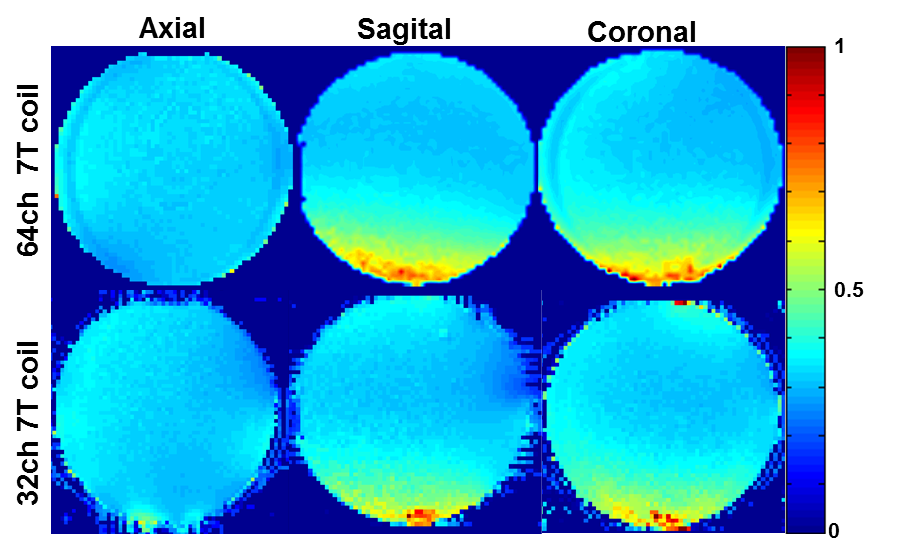
Data were acquired on clinical 7T whole-body MRI scanner (MAGNETOM Terra, Siemens Healthcare, Erlangen, Germany) using the 17cm spherical loading “BIRN” agar phantom [5]. Array noise covariance was estimated from thermal noise data acquired without RF excitation, and SNR maps were computed following the method of Kellman & McVeigh [6]. The B1+ map was acquired using the AFI [7] Method (64x64x56 matrix, FOV= 192x192x168 mm, TRs= [5.8, 28] ms, Flip angle 60º, TE=2.73 ms, BW=260Hz/pixel) using an oil phantom to determine B1 homogeneity of the volume transmit coil. The coil was then compared to a 32-Channel receive array whose helmet and the transmit birdcage are of the same dimensions.
Results
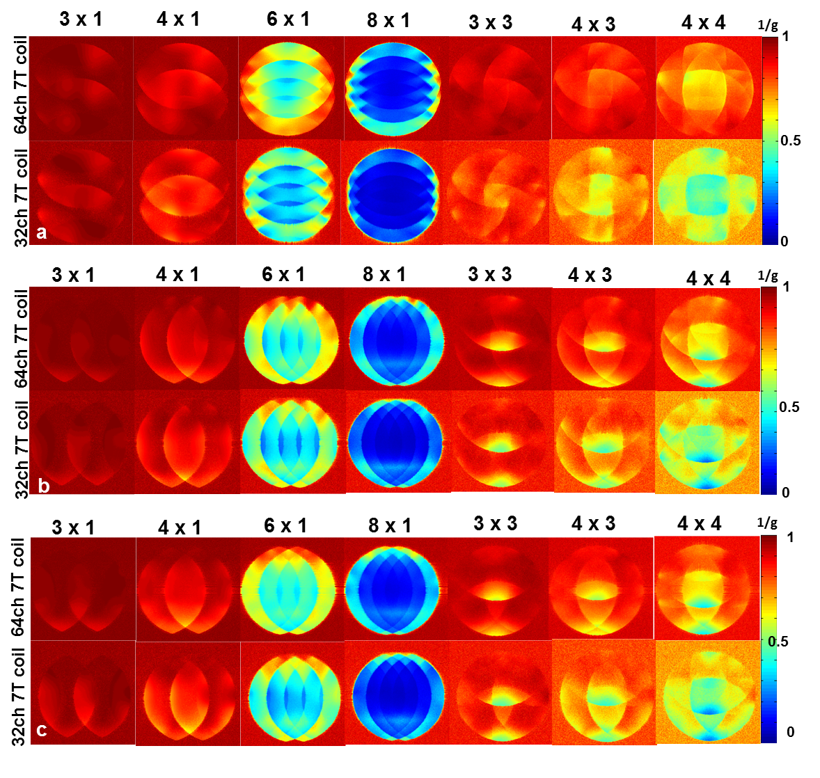
Each element shows a Q unloaded-to-loaded (with a human head) ratio of ~260/40. S21, loaded, between neighboring elements ranges from -18 dB to -10.5 dB. S11 reflections showed the elements tuned and matched to the 75 Ω required by the preamplifier. Fig. 2a shows unaccelerated SNR maps of the BIRN phantom comparing the 64 and 32 channel arrays in the three orientations. The SNR gain in the axial slice ranges from 2.4-fold on the phantom’s edge to approximately no-gain at the center. In the sagittal and coronal slice the SNR gain at the edge was up to 1.5x and 3x respectively. Figure 2b shows the noise correlation matrix between channels. Average was 8% for the 64-channel coil, which is lower than the 32ch but with comparable peak couplings. The g-factor comparison (Fig. 3) shows that the 64-channel coil and the 32-channel coil are comparable for low accelerations but the 64 channel starts to perform better at 1D accelerations above 3 fold and 2D accelerations of 3x3 and above. The B1+ map in Fig 4 shows relatively uniform transmit efficiency over the oil phantom and similar to the 32-channel array, demonstrating a minimal shielding effect from the densely arranged preamps around the receive coil.Discussions and Conclusion
The current system incorporates an improved mechanical design, preamps mounted above the coil detectors, and an integrated transmit coil design to provide highly accelerated brain imaging for UHF MR studiesAcknowledgements
Thanks to Simon Sigalovsky for help with fabrication. Thanks to Bernd Stoeckel from Siemens Medical Solutions, USA for help with coil files. Thanks to Danny Joseph Park for help with setting up the protocols. Thanks to Neha Koonjoo for help.References
[1] Keil et al., MRM 2013, 70 (248-258). [2] Ugurbil et al., MRM 2019 (1-15) [3] Wiesinger et al. MRM 2004 52(5) 953-964 [4] Keil et al. MRM 2011, 66(6): 1777-87 [5] https://www.dropbox.com/s/u50k8yp11c46r32/BIRN_phantom.pdf?dl=0 [6] Kellman et al. MRM 2005, 54(6): 1439-47 [7] Yarnykh et al. (2007) MRM 57(1):192-200.Figures
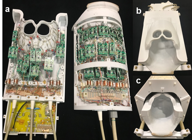
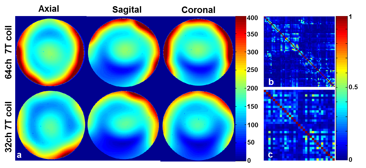
Fig 2. (a) SNR map using a spherical Agar BIRN Phantom. The SNR gain in the axial slice ranges from 2.4-fold on the phantom’s edge to approximately no-gain at the center. In the sagittal and coronal slice the SNR gain at the edge was as high as 1.5x and 3x respectively; (b) Noise Correlation matrix of 64-channel coil: Average 8%; (c) Noise Correlation matrix of 32-channel coil: Average 12%