0763
Assessment of MR compatibility for multichannel stimulation using three-axis TMS coil elements1Radiology, A.A Martinos Center for Biomedical Imaging/MGH, Charlestown, MA, United States, 2Harvard Medical School, Boston, MA, United States, 3Tristan Technologies, San Diego, CA, United States, 4Department of Electrical and Computer Engineering, A.A Martinos Center for Biomedical Imaging/MGH, Worcester, MA, United States, 5HST/MIT, Cambridge, MA, United States
Synopsis
We investigate the feasibility of using small-diameter three-axis TMS coil as a basis for constructing a simultaneous stimulation and imaging array. We present an MR-compatible 3-axis TMS coil prototype comprising of three orthogonal coil X/Y/Z units. We assess the influence of the TMS coil element on the MRI images and measure the sound pressure levels with systematically varying the current amplitudes and coil orientation with respect to the magnetic field. Supported by simulations, we conclude that construction of a large-scale multichannel; system using such a 3-axis TMS elements as a basis appears feasible but the acoustic properties should be improved
Introduction
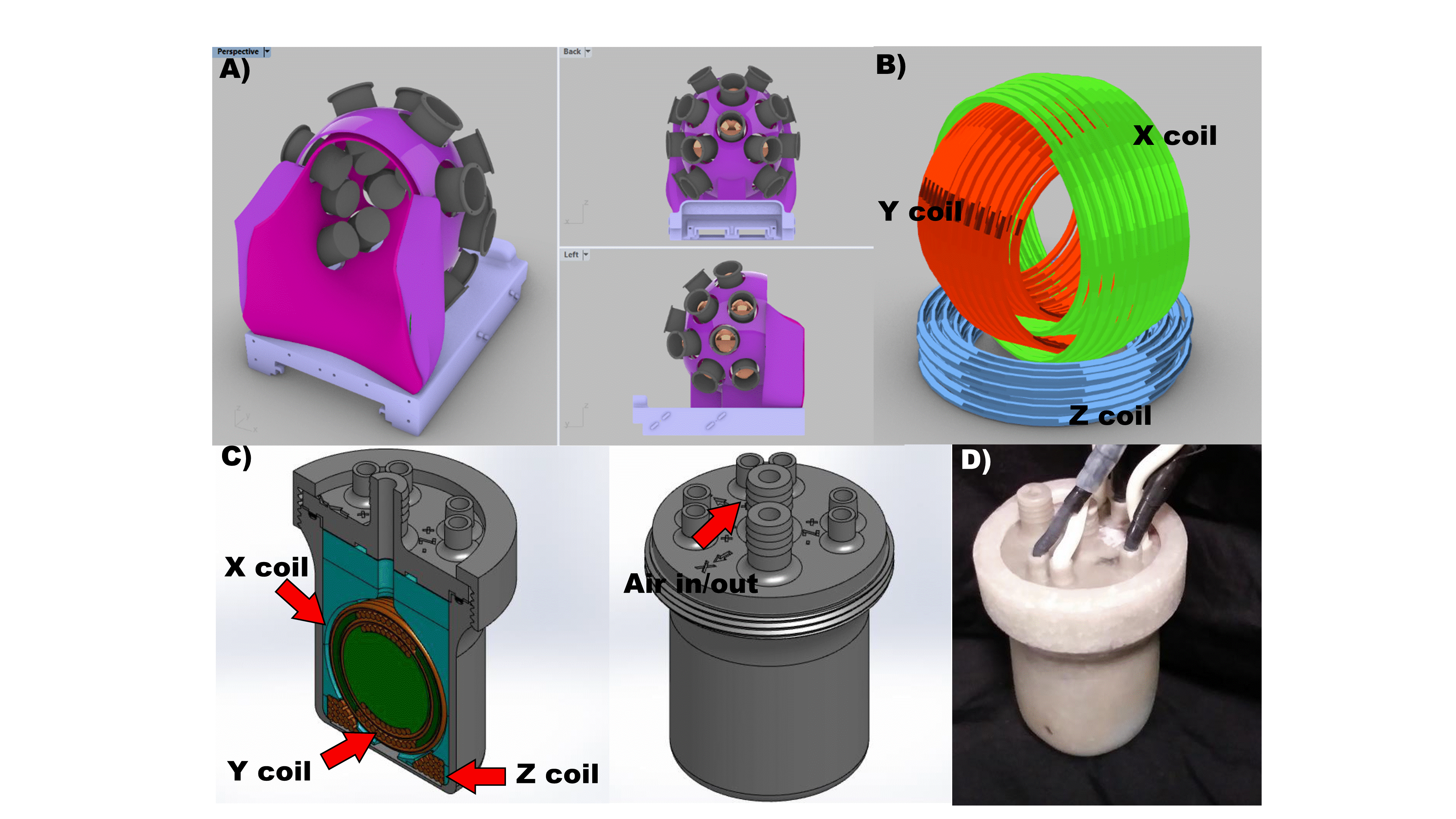
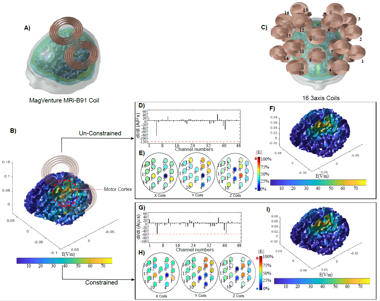
Multichannel Transcranial Magnetic Stimulation (mTMS) is an emerging technology for non-invasive stimulation of the human brain. The use of multiple TMS coils in an array configuration enables shifting the location TMS ‘hot spot’ electronically without any mechanical movement. This is achieved by computationally determining the current amplitudes to be passed to each of the coil elements to synthesize a desired target field pattern1. The mTMS technique would be particularly powerful when used in conjunction with functional MRI (fMRI), since maneuvering multiple TMS coils inside the scanner environment either manually or robotically becomes rather cumbersome. While the combination of TMS and fMRI has been demonstrated2 and subsequently optimized in terms of TMS-compatible RF receive coil arrays3, the main challenge is that for maximizing the degrees of freedom for the mTMS targeting approach, multiple coil elements need to be employed that are smaller than the conventional MR-compatible coils, resulting in significantly increased current densities and magnetic fields. Here, our goal was to fabricate a small diameter ‘three-axis’ TMS coil (See Fig.1B) that is proposed to be used in a large-scale integrated mTMS/MRI system (Fig.1A) that is currently under development. Subsequently, we evaluated the compatibility with 3T MR environment. Finally, we assessed whether a 16x3=48 channel TMS array could be used to synthesize electric field patterns suitable for stimulating the motor cortex.Methods
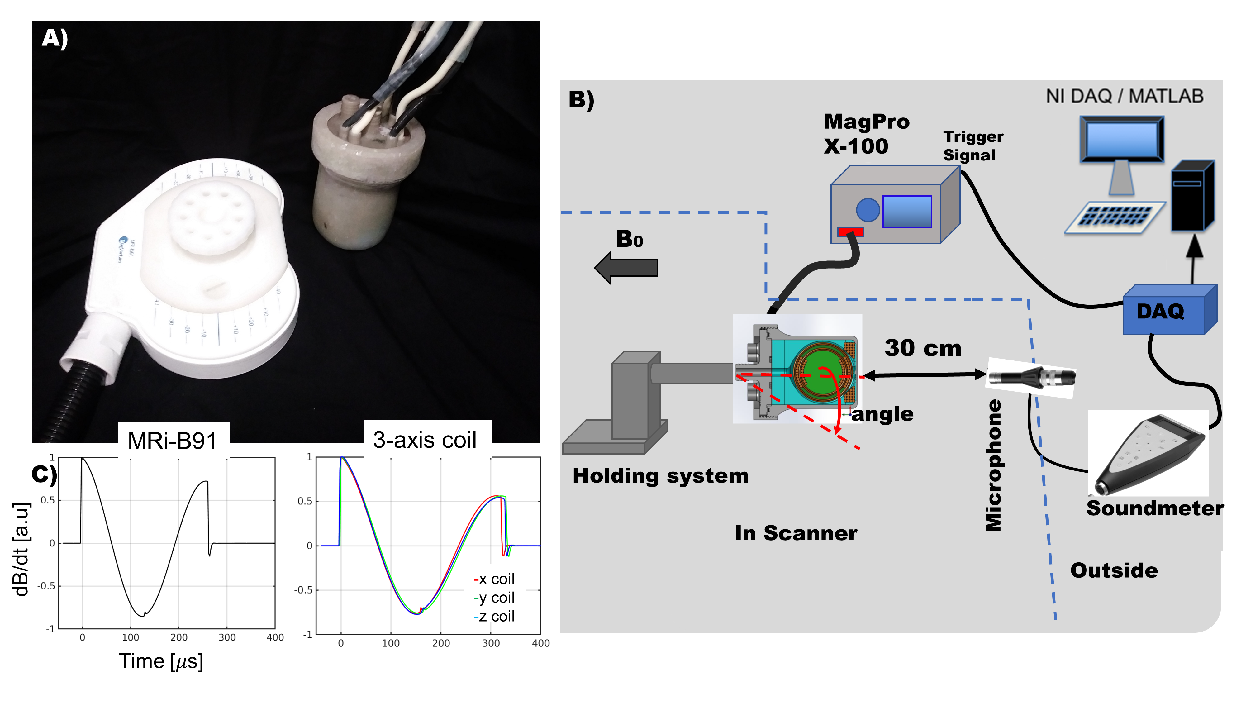
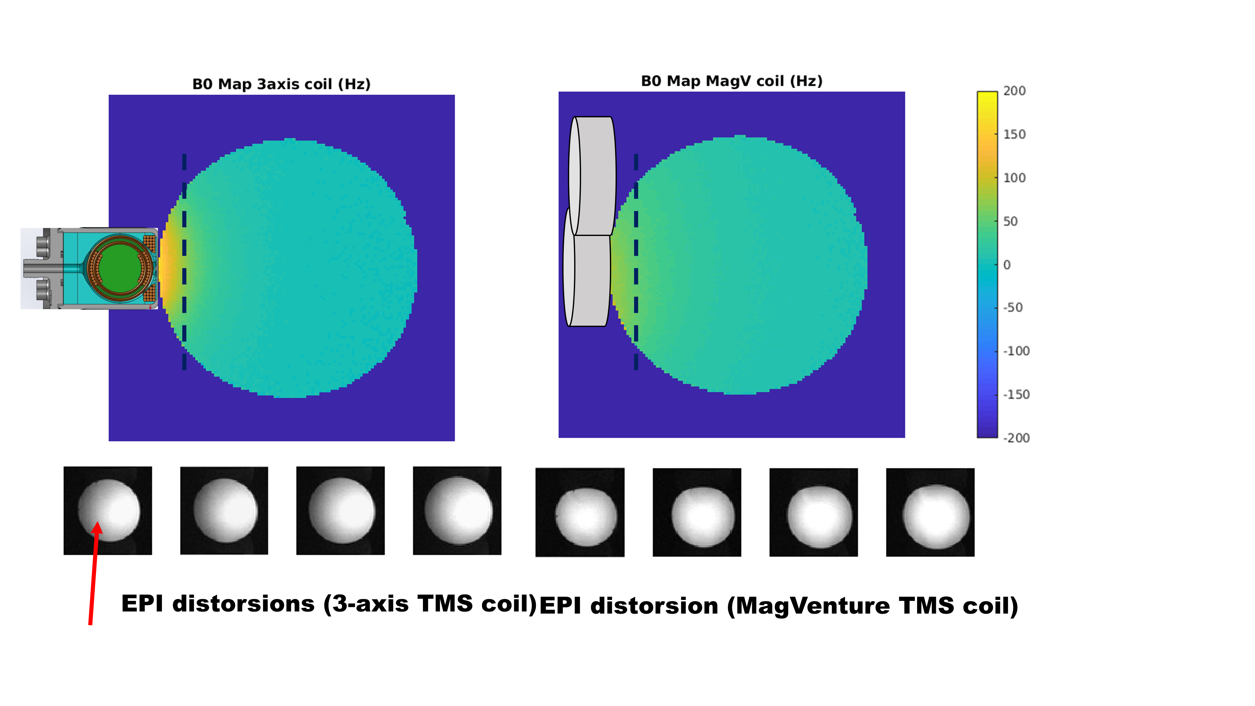
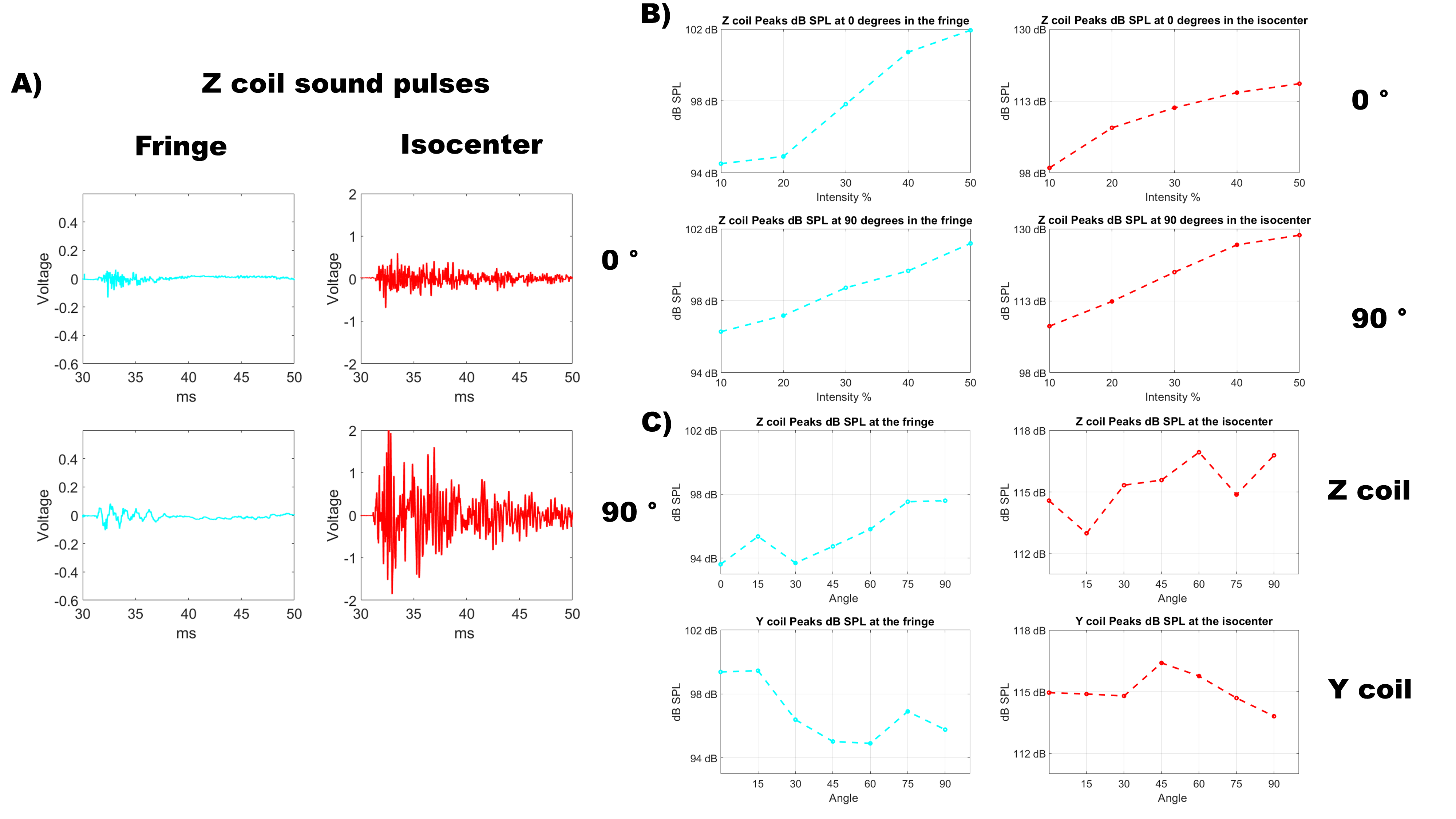
An MRI compatible 3-axis TMS coil was fabricated (see a 3D-CAD model in Fig1.C) employing vibration damping material (blue material in the figure) to mechanically decouple the X/Y and Z coil elements while allowing cooling air to flow in/out through the coil assembly. The coil embedded in the damping material was then encapsulated in an epoxy-fiberglass chassis to harden the structure. The final prototype is shown in Fig.1D. The 3-axis TMS coil and the commercial MR compatible TMS (MRi-B91, MagVenture, Denmark) (see Fig2.A) were evaluated in terms of B0 effects acquiring GRE field map sequence (FOV 220mm, 75 slices, FA=75, TR=1200ms, TE1=10ms, TE2=12.64ms, SL=2mm, 1.7mm in-plane resolution, axial). To assess the possible drop-outs/distortions on the functional images, EPI images (FOV=200mm, SL=5mm, TR=1710ms, TE=31ms, FA,90, 24 slices , 2.3mmx2.3mm in-plane resolution) were acquired of a 19 cm standard spherical phantom placing the TMS coils on the top of the phantom. B0 maps were calculated using MATLAB and displayed in Hz. To perform an assessment of the acoustic noise produced by the new developed coil, sound pressure levels were acquired using an MR compatible microphone and the corresponding sound meter (2238 Mediator, Bruel & Kjaer, Denmark). See measurement setup in Fig2.B. Sound pressure waveforms were acquired using the NI 6341 (National Instruments, USA) and evaluated as Peak dB (20log(Pin/Pref) dB) in MATLAB. First, sound increase depending on stimulation intensity was investigated for the Z coil at fringe and at isocenter. Then, at 25% of maximal stimulator output (MSO) (100% = 1800 V stimulator charging voltage), the effect of the angle between the Z coil normal and the B0 in the sound was evaluated for Z and Y coils, for both cases, at fringe and isocenter. Finally, we simulated a 16x3 = 48 channel mTMS system using an anatomically realistic model of a human head. We used the minimum-norm approach1 with and without constrained optimization to determine the current amplitudes to synthesize the electric fields corresponding to a commercially available TMS coil.Results
B0 maps and EPI images are shown in Fig3. Standard deviation for the 3-axis TMS coil was 1.27 Hz and for the MagVenture coil 0.67Hz. Results of the sound evaluation are summarized in Fig4. using the absolute sound pressure level peak as the measure. For comparison, the maximal values reported by the sound meter (time windowing of 10ms and frequency weighting) were 113.9 dB for the Z coil in the fringe with 90° at 50 %. For the MagVenture coil, the maximal sound pressure level recorded was 104.8 dB for 100% and 90°. The capability of the multichannel system to ‘emulate’ the commercial MRI-compatible TMS coil shown in Fig 5. The E-fields of the MRi-B91 coil are shown for current rate-of-change (dI/dt) of 94 A/µs that corresponds to 50%MSO (Fig.5 A-B). The dI/dt values required to synthesize the corresponding field using the 16x3 array (Fig.5C) were calculated either with no constraint (maximal achievable dI/dt =120A/µs) (Fig.5D-E) or constrained minimum-norm optimization (dI/dt < 60 A/µs = 50% MSO) (Fig.5G-H). In each of the cases, the desired E-field could be synthesized but in the constrained case more channels with reduced amplitudes were used.Discussion
We demonstrated the feasibility of constructing an MR-compatible three-axis TMS coil that can be utilized as a basic element in a large-scale hybrid mTMS/MRI system. The B0 artefacts imply that the materials selected are well suited for concurrent TMS/MRI. The acoustic noise from the current three-coil prototype is reaching the limits of EPI gradient switching noises4 and substantially larger than the large-diameter MRi-B91. However, our current coil prototype does not yet incorporate any materials for muffling the sound from the coils, which is expected to reduce the sound levels significantly. In conclusion, our results support the feasibility of constructing an MR-compatible multichannel system using the three-axis coil as a basic element.Acknowledgements
This work was funded by NIH R00EB015445, R01MH111829, NIH R00EB021349.References
(1) Ruohonen J and Ilmoniemi R. Medical and Biological Engineering and Computing, Vol. 36 p297-301,1998
(2) Bohning et al.,Invest Radiol,33(6):336-340,1998
(3) Navarro de Lara et al., MRM, 74(5), p.1492(10), 2015
(4) Ravicz et al., J Acoust Soc Am. 108(4): 1683–1696; October
Figures