0762
Design of transmit array coils for MRI by minimizing the modal reflection coefficients1Electrical and Electronics Engineering Department, Bilkent University, Ankara, Turkey, 2National Magnetic Resonance Research Center (UMRAM), Bilkent University, Ankara, Turkey
Synopsis
We propose a general analysis based on minimization of modal reflection coefficients, providing a simple tool for quantifying the performance of transmit array (TxArray) coils in terms of power efficiency. We investigate the performance of various dual-row birdcage TxArrays, with an additional degree of freedom to correct B1+-field inhomogeneities by adding RF shimming ability in the longitudinal-direction, together with simulations and experiments. The chosen structure of the TxArray allows the coil to act like degenerate birdcage coils. We demonstrate when TxArrays are properly designed, in some critical excitation modes such as circularly-polarized (CP) mode, the total reflection becomes negligibly small.
Introduction
Transmit arrays (TxArrays) are being widely investigated for ultra-high field systems to improve B1-field uniformity1,2. These coils can be also useful for conventional scanners by providing an additional degree of freedom, enable RF shimming while trying to minimize local SAR3,4, increase power efficiency5,6, or implement implant-friendly modes7.High coupling between the TxArray elements causes extra losses leading to an increase in power consumption and this is a major design issue. The problem of coupling reduction gets more difficult to solve as the number of elements increases6,8. For TxArrays which are not perfectly decupled, the active reflection efficiency9, which is defined as the total reflected to incident power ratio, depend on the phases/amplitudes of power amplifiers, besides being dependent upon levels of matching and decoupling. Although multiple studies focused on optimizing the excitation profiles under multiple strict constraints including power consumption of TxArrays6,10-13, special attention needs to be paid to categorize the inputs based on the reflected power from TxArrays.
In this study, we aim to examine the feasibility of a novel technique based on the eigenmode analysis of $$${\bf{S}}$$$-matrix to find the set of inputs with high power efficiencies and investigate the performance of a dual-row birdcage TxArray as an efficient and highly homogeneous coil for imaging at 123.2MHz. In the design process of TxArrays, we utilize the insight provided by eigenmode analysis to minimize the total reflected power for a larger group of driving voltages by adjusting TxArray’s free parameters instead of focusing on the matching and decoupling levels which were considered previously14-19.
Methods
We simulated four TxArrays and four birdcage coils using the co-simulation strategy20, all with the same overall dimensions (Figure1). TxArray’s transmit loops could be decoupled by the adjustment of capacitors placed between nearest neighbors. The birdcage-like currents which produce the uniform excitation can be derived with exciting both rows individually in the circularly-polarized (CP) mode, while the currents of the upper- and lower-rows cancel each other in their mutual-ring segments.TxArray can be characterized using $$${\bf{S}}$$$-matrix, where $$${{\bf{V}}^-}={\bf{S}}{{\bf{V}}^+}$$$, to quantify how RF power propagates through the ports.$$${{\bf{V}}^+}$$$ and $$${{\bf{V}}^-}$$$ are vectors of the incident and reflected voltages. Suppose that the $$$n$$$th eigenvalue and eigenvector of $$${{\bf{S}}^{\bf{H}}}{\bf{S}}$$$ are $$${\lambda_n}$$$ and $$${{\bf{V}}_n}$$$ which satisfy $$$\left[{{{\bf{S}}^{\bf{H}}}{\bf{S}}}\right]{{\bf{V}}_n}={\lambda_n}{{\bf{V}}_n}$$$. If TxArray is excited in such a way that $$${{\bf{V}}^+}={{\bf{V}}_n}$$$, then:
$$\begin{array}{l}{{\bf{V}}^-}^{\bf{H}}{{\bf{V}}^-}={\bf{V}}_n^{\bf{H}}{{\bf{S}}^{\bf{H}}}{\bf{S}}{{\bf{V}}_n}\\\,\,\,\,\,\,\,\,\,\,\,\,\,\,\,\,={\bf{V}}_n^{\bf{H}}{\lambda_n}{{\bf{V}}_n}\\\,\,\,\,\,\,\,\,\,\,\,\,\,\,\,\,={\lambda_n}{{\bf{V}}^+}^{\bf{H}}{{\bf{V}}^+}\end{array}$$
Therefore the active reflection efficiency of$$${{\bf{V}}_n}$$$ can be described as:
$$\lambda({{\bf{V}}_n})=\frac{{P_{Total}^r}}{{P_{Total}^i}}=\frac{{{{\bf{V}}^-}^{\bf{H}}{{\bf{V}}^-}}}{{{{\bf{V}}^+}^{\bf{H}}{{\bf{V}}^+}}}={\lambda_n}$$
That’s why$$${\lambda_n}$$$ and$$${{\bf{V}}_n}$$$ shall be called the $$$n$$$th modal reflection coefficient and modal excitation vector of TxArray. The active reflection efficiency for an arbitrary incident voltage which is expanded by the modal excitation vectors,i.e.$$${{\bf{V}}^+}={w_1}{{\bf{V}}_1}+{w_2}{{\bf{V}}_2}+\cdots+{w_{2N}}{{\bf{V}}_{2N}}$$$, can be expressed as:
$$\lambda({{\bf{V}}^+})=\frac{{\sum\limits_{n=1}^{2N}{{\lambda_n}|{w_n}{|^2}}}}{{\sum\limits_{n=1}^{2N}{|{w_n}{|^2}}}}$$
Consequently, the capacitors can be adjusted to minimize all modal reflection efficiency to achieve a low active reflection efficiency for a larger set of incident voltages. In this work,$$${{\bf{V}}_n}$$$ associated with $$${\lambda_n}\le0.5$$$ were considered as an efficient mode.
Results
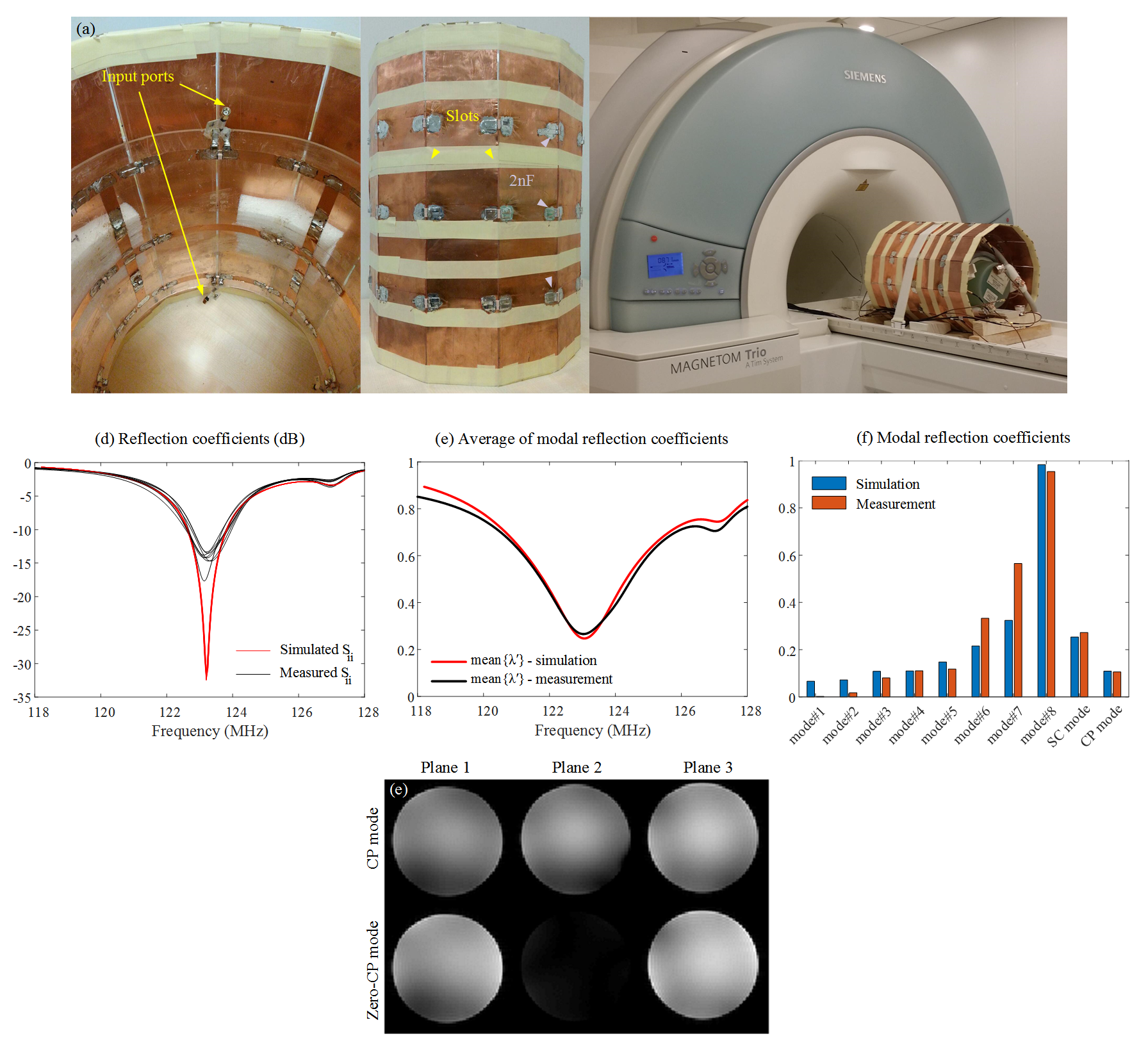
The TxArray performances for different sets of capacitor values acquired by four optimization approaches was summarized in Table1. In Opt#1 and Opt#2, mean{$$${\lambda^2}$$$} and $$${\lambda_{CP}}$$$ were minimized, while Opt#2 restricted $$${\lambda_{CP}}$$$ to below 0.01. In Opt#3, just mean{$$${\lambda^2}$$$} was minimized. In Opt#4, the matching and decoupling levels were maximized. Three solutions obtained for the 2×4-channel TxArray showed that limiting $$${\lambda_{CP}}$$$ could raise mean{$$$\lambda$$$} by 18.1%, while neglecting $$${\lambda_{CP}}$$$ could decrease mean{$$$\lambda$$$} by 2.6%. The solution obtained by Opt#4 for 2×8-channel TxArray could increase mean{$$$\lambda$$$} and $$${\lambda_{CP}}$$$ by 13.3% and 50.1% compared to the solution provided by Opt#1. The solution acquired by Opt#1 also offers 9 efficient modes, while the solution obtained by Opt#4 contains 6 efficient modes.Figure2a shows the surface current density on the 2×4-channel TxArray and $$${\bf{B}}_{\bf{1}}^+$$$-maps for three excitation modes. In the SC mode, only one single-channel is excited. In the CP mode, the middle-ring current is almost zero which provides a uniform $$${\bf{B}}_{\bf{1}}^+$$$-profile in Plane#2. The Zero-CP mode provides a zero $$${\bf{B}}_{\bf{1}}^+$$$-field in Plane#2 with homogeneous profiles in other planes. In this mode, both rows excited in the CP mode and the middle-ring currents amplify instead of canceling each other. Figure2b shows $$${\bf{B}}_{\bf{1}}^+$$$-profiles of modal excitation vectors, and the SC and CP excitation modes. Figure2c indicates where the incident power is consumed.
Figure3a indicates $$${\bf{B}}_{\bf{1}}^+$$$-profiles of the 2×4-channel TxArray and the 4-rung birdcage coil in the CP mode by showing mean±SD. Figure3(b-d) provide the active reflection efficiency, the delivered power to the phantom, and the transmit efficiency of 2×N-channel TxArray and N-rung birdcage coils with N=4,8,12,16. As N increases, the reflected power in the SC mode increases. However, if TxArrays are properly designed, low active reflection efficiencies can be achieved for some critical excitations.
To validate the simulations, the 2×4-channel TxArray designed based on Opt#1 was constructed (Figure4a). The simulated and measured reflection coefficients, mean{$$$\lambda$$$}, and modal reflection coefficients are shown in Figure4(b-d). Figure4e shows the GRE images in the CP and Zero-CP modes.
Conclusion
Eigenmode analysis is a convenient way to complement the S-matrix analysis which intuitively provides a compact representation of TxArray’s transmission capabilities, gives us tremendous insight into the question of what are the excitation sets with the low level of reflected power, and offers a simple tool for quantifying, comparing, and optimizing the performance of TxArrays.Acknowledgements
References
1. Adriany G, Van de Moortele PF, Wiesinger F, Moeller S, Strupp JP, Andersen P, Snyder C, Zhang X, Chen W, Pruessmann KP, Boesiger P, Vaughan T, Uğurbil K. Transmit and receive transmission line arrays for 7 Tesla parallel imaging. Magn Reson Med. 2005 Feb;53(2):434-45.
2. Adriany G, Auerbach EJ, Snyder CJ, Gözübüyük A, Moeller S, Ritter J, Van de Moortele PF, Vaughan T, Uğurbil K. A 32-channel lattice transmission line array for parallel transmit and receive MRI at 7 tesla. Magn Reson Med. 2010 Jun;63(6):1478-85.
3. Van den Berg CA, Van den Bergen B, Van de Kamer JB, Raaymakers BW, Kroeze H, Bartels LW, Lagendijk JJ. Simultaneous B1+ homogenization and specific absorption rate hotspot suppression using a magnetic resonance phased array transmit coil. Magn Reson Med. 2007 Mar;57(3):577-86.
4. Katscher U, Börnert P. Parallel RF transmission in MRI. NMR Biomed. 2006 May;19(3):393-400.
5. Childs AS, Malik SJ, O'Regan DP, Hajnal JV. Impact of number of channels on RF shimming at 3T. MAGMA. 2013 Aug;26(4):401-10.
6. Guérin B, Gebhardt M, Serano P, Adalsteinsson E, Hamm M, Pfeuffer J, Nistler J, Wald LL. Comparison of simulated parallel transmit body arrays at 3 T using excitation uniformity, global SAR, local SAR, and power efficiency metrics. Magn Reson Med. 2015 Mar;73(3):1137-50.
7. Eryaman Y, Guerin B, Akgun C, Herraiz JL, Martin A, Torrado-Carvajal A, Malpica N, Hernandez-Tamames JA, Schiavi E, Adalsteinsson E, Wald LL. Parallel transmit pulse design for patients with deep brain stimulation implants. Magn Reson Med. 2015 May;73(5):1896-903.
8. Mahmood Z, Guérin B, Adalsteinsson E, Wald LL, Daniel L. An automated framework to decouple pTx arrays with many channels. Proc. Intl. Soc. Mag. Reson. Med. 21, 2013.
9. Ludwig A. Mutual coupling, gain and directivity of an array of two identical antennas. IEEE Trans. Antennas Propag., vol. AP-24, no. 6, pp. 837–841, Nov. 1976.
10. Guérin B, Setsompop K, Ye H, Poser BA, Stenger AV, Wald LL. Design of parallel transmission pulses for simultaneous multislice with explicit control for peak power and local specific absorption rate. Magn Reson Med. 2015 May;73(5):1946-53.
11. Guérin B, Gebhardt M, Cauley S, Adalsteinsson E, Wald LL. Local specific absorption rate (SAR), global SAR, transmitter power, and excitation accuracy trade-offs in low flip-angle parallel transmit pulse design. Magn Reson Med. 2014 Apr;71(4):1446-57.
12. Brunner DO, Pruessmann KP. Optimal design of multiple-channel RF pulses under strict power and SAR constraints. Magn Reson Med. 2010 May;63(5):1280-91.
13. Vaughan JT, Garwood M, Collins CM, Liu W, DelaBarre L, Adriany G, Andersen P, Merkle H, Goebel R, Smith MB, Ugurbil K. 7T vs. 4T: RF power, homogeneity, and signal-to-noise comparison in head images. Magn Reson Med. 2001 Jul;46(1):24-30.
14. Avdievich NI, Giapitzakis IA, Pfrommer A, Shajan G, Scheffler K, Henning A. Decoupling of a double-row 16-element tight-fit transceiver phased array for human whole-brain imaging at 9.4 T. NMR Biomed. 2018 Sep;31(9):e3964.
15. Kazemivalipour E, Sadeghi-Tarakameh A, Yilmaz U, Acikel V, Sen B, Atalar E. A 12-channel degenerate birdcage body transmit array coil for 1.5T MRI scanners. In Proceeding of the 26th Joint Annual Meeting ISMRM-ESMRMB, 2018.
16. Kazemivalipour E, Sadeghi-Tarakameh A, Atalar E. Optimization of the degenerate birdcage transmit array coil for minimum coupling. In Proceeding of the 27th Joint Annual Meeting ISMRM, 2019.
17. Shajan G, Kozlov M, Hoffmann J, Turner R, Scheffler K, Pohmann R. A 16-channel dual-row transmit array in combination with a 31-element receive array for human brain imaging at 9.4 T. Magn Reson Med. 2014 Feb;71(2):870-9.
18. Yan X, Pedersen JO, Wei L, Zhang X, Xue R. Multichannel Double-Row Transmission Line Array for Human MR Imaging at Ultrahigh Fields. IEEE Trans Biomed Eng. 2015 Jun;62(6):1652-9.
19. Hoffmann J, Shajan G, Scheffler K, Pohmann R. Numerical and experimental evaluation of RF shimming in the human brain at 9.4 T using a dual-row transmit array. MAGMA. 2014 Oct;27(5):373-86.
20. Kozlov M, Turner R. Fast MRI coil analysis based on 3-D electromagnetic and RF circuit co-simulation. J Magn Reson. 2009 Sep;200(1):147-52.
Figures