0759
BPSK/ASK Wireless Link Assessment for MRI1Electrical Engineering, Stanford University, Stanford, CA, United States, 2Stanford University, Stanford, CA, United States, 3GE Healthcare, Aurora, OH, United States
Synopsis
We assess the use of binary phase shift keyed and amplitude shift keyed modulation to develop a very short range wireless link. Here the signal integrity for transmission of 200 Mbps at 3.2 GHz carrier frequencies were demonstrated in a mock MRI bore environment. This approach provides a viable path for wireless MRI receive coil data transfer.
Introduction
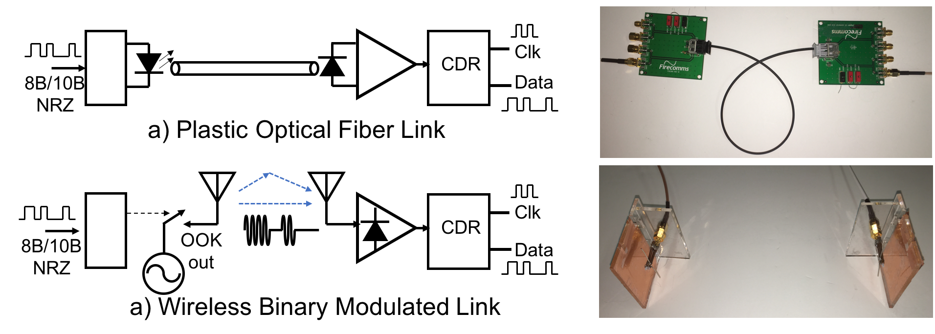
For modern high density receive arrays [1,2], traditional cable layout creates a bottleneck for wearability and conformability because of the unpredictability in coil-cable coupling, indirect preamp oscillation and cable trap heating. A completely wireless coil interface would eliminate the cable bulk and handling issues. Demonstrated subsystems needed for wireless MRI include wireless power transfer [3], wireless Q-spoiling [4], and phase synchronization [5]. Several strategies for digital data transfer include the WiFi and WiGig standards but these would require a wearable embedded linux module for operation. On-Off keyed (OOK) milli-meter wave data transmission [6] has been demonstrated at 60 GHz, but requires further IC development. The key to mm-wave OOK was the large spectral bandwidth availability. An interesting alternative is the design of a very short wireless replacement of a “virtual” 200 Mbps plastic optical fiber link (Fig. 1). We explore the signal integrity feasibility of achieving a 200 Mbps link at 3.2 GHz with simple binary modulation (BPSK, DPSK, ASK, OOK).Methods
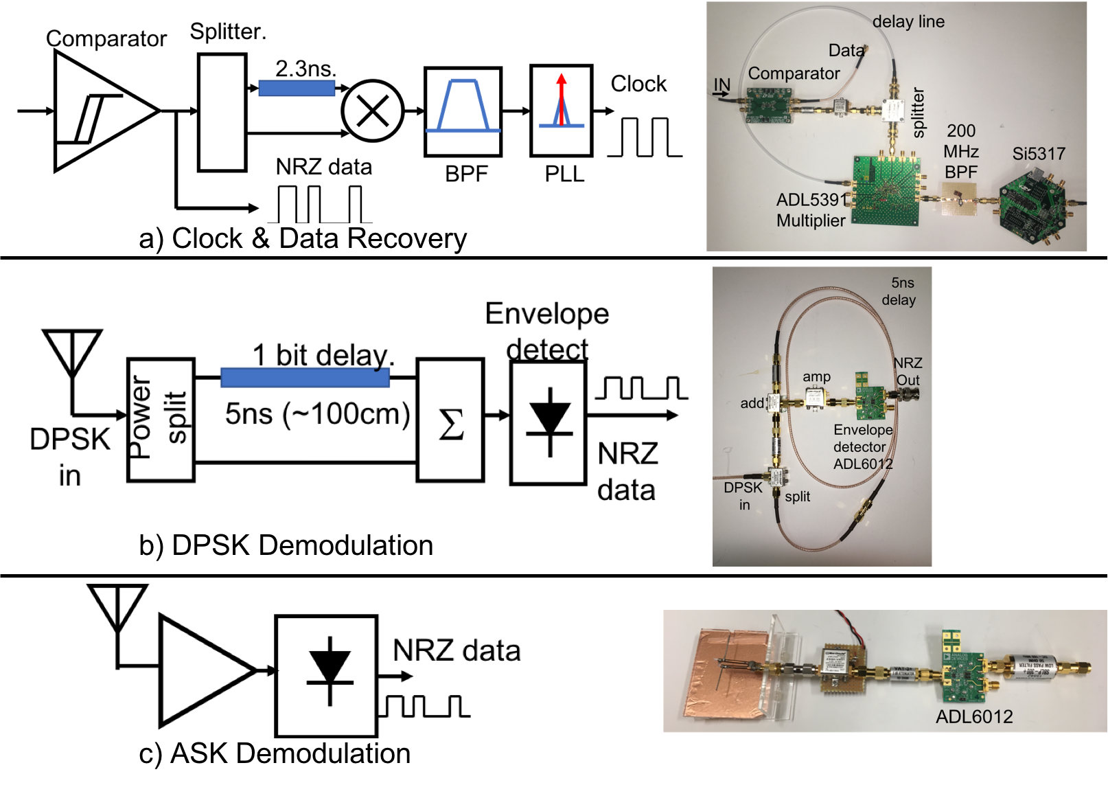
Binary phase shift keyed (BPSK) and amplitude shift keyed (ASK) modulators were constructed using the LTC5510 mixer eval board (DC1984A) and a 3.2 GHz cylindrical resonator oscillator (Crystek) (Fig 2). For BPSK, the mixer simply reverses the signal phase at 200 Mbps. For ASK, additional power combiners and splitters coherently add in the unmodulated carrier to synthesize an on-off keyed (OOK) signal waveform.The RF signal demodulation signal chains are shown in Figure 3. First, clock and data recovery (CDR) requires a fast comparator (LTC6957)to convert the analog demodulated signal to a logic level. A delayed version of this is self-multiplied by a ADL5391 multiplier followed by a 200 MHz bandpass filter and Si5317 jitter cleaner. For BPSK demodulation, we actually implemented a differential phase shift keyed (DPSK) demodulator which uses a time delay discriminator. Here a signal path is split and time delayed by one bit period. This is then coherently added to the present bit and envelope detected by an ADL6012. This approach avoids the need for synchronous demodulation. For ASK demodulation, the 3.2 GHz RF waveform is amplified and fed directly to the envelope detector. For the DPSK and ASK demodulators, the envelope detector output is filter by a 300 MHz linear time delay low-pass filter before the CDR stage. Simple dipole antennas were constructed for 3.2 GHz but use an approximate quarter-wave reflector to improve directivity. For testing, these antennas were placed in a mock whole body MRI bore that included the RF shield and birdcage resonator.
Results
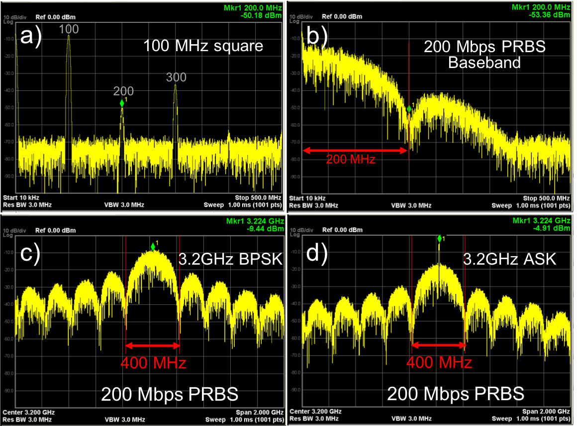
The modulation spectra are shown in Fig. 4. For reference, a 100 MHz square wave (a) is shown which can be considered as a 200 Mbps pattern of repeating 01s. Signal nulls are at multiples of 200 MHz. In b) a pseudo random binary sequence (PRBS) at 200 Mbps is shown, which retains nulls at integer multiples of the bit rate. When the PRBS data is BPSK modulated by a 3.2 GHz carrier (c), the main lobe spans 400 MHz and significant spectral energy occupies over 800 MHz. For ASK, the spectral distribution is of equal span, but must be at least 6dB lower, since the signal source power is now also used to transmit a carrier.For final transmission testing, a volunteer was placed in the mock MRI bore with modulator and transmit antenna on the chest. The receive antenna was attached the birdcage cylinder surface. Figure 5a shows the experimental setup. Figure 5b,c show respectively the demodulated analog eye diagram, as well as the output of the clock & data recovery system. We see that for both the DPSK and ASK demodulation, the eye patterns are very wide, indicating considerable SNR and jitter head-room. The short link distances have good signal integrity to support the 200 Mbps test patterns.
Discussion
In these tests, our instrumentation was limited to 200 Mbps PRBS generation. However, based upon our present results, 250 Mbps should be attainable. One of the key outcomes of this feasibility study is that a specialized IC development can be avoided since there are no size limitations for the data receive chain. For signal transmission, an oscillator and mixer replace their optical LED equivalent. However, much like high speed optical transmission, the data will need to be 8B/10B encoded to ensure sufficient bit transitions occur to maintain CDR performance. Importantly, since MRI operates in a RF shielded environment, we are not limited to the ISM bands of WiFi and Bluetooth. It should be possible to have multiple modulators separated by around 1 GHz to enable a few short link channels. In future, a key development will be the miniaturization and integration of the modulator components on-coil.Conclusion
Rudimentary BPSK and ASK modulation/demodulation systems were developed and demonstrated short wireless link viability for 200 Mbps data rates. In this work, these short links can be thought of as a virtual wireless serial link replacement of a short optical link. The approach avoids the need for development of custom RF ICs, and provides a viable path for Wireless MRI receive arrays.Acknowledgements
We thank GE Healthcare for research support and NIH 1RO1 EB019241. We would like to thank Thomas Grafendorfer for his assistance.
References
1. A Semiflexible 64-channel receive-only phased array for pediatric body MRI at 3T, Tao Zhang et al, Magnetic Resonance in Medicine, DOI: 10.1002/mrm.25999.
2. "Screen-Printed Flexible MRI Receive Coils" by Joseph R Corea et al Nature Communications, 7, 10839, March 10, 2016.
3. An MRI Compatible RF MEMs Controlled Wireless Power Transfer System” by Byron K et al, IEEE Trans. Microwave Theory Techniques, 67(5),1717-1726, May 2019. DOI:10.1109/TMTT.2019.2902554.
4. Depletion-Mode GaN HEMT Q-Spoil Switches for MRI Coils, Lu JY et al, IEEE Trans. Med. Imaging, 35(12), p2558, Dec. (2016). PMID:548872
5. Software Synchronization of Independent Receivers by Transmit Phase Tracking Greig Scott et al Proc 25th ISMRM, Honolulu, April 2017, p4311.
6. A Millimeter-Wave Digital Link for Wireless MRI, Aggarwal K et al. IEEE Trans. Med. Imaging, 36(2), p574-583, Feb. (2017). PMID:5709036
Figures
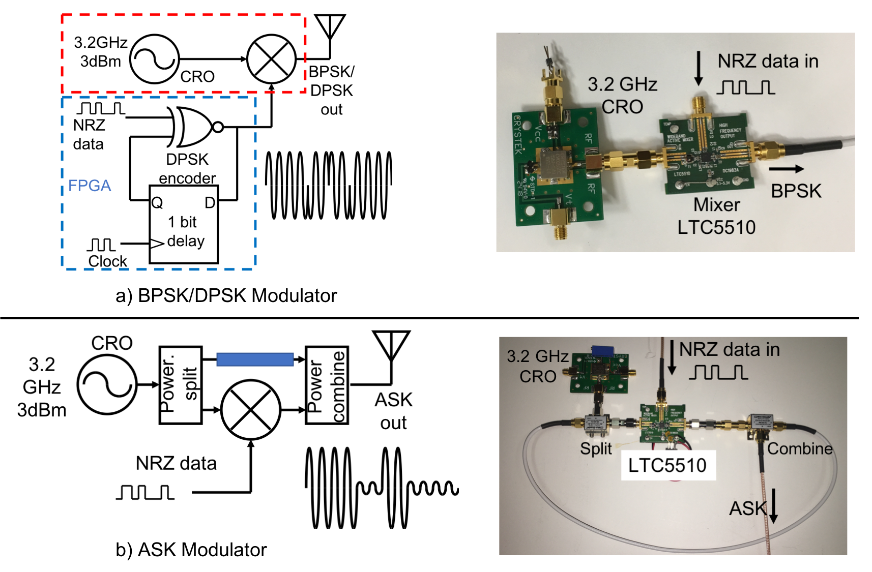
a) Binary phase shift keyed (BPSK) modulator constructed using LTC5510 mixer and a 3.2 GHz cylindrical resonator oscillator, with 3dBm output power.
b) Amplitude shift keyed (ASK) modulator adds in power splitter and combiner signals to the core BPSK modulation to coherently add/subtract the carrier. In the ideal case, this mimics an On-Off keyed modulation (OOK).
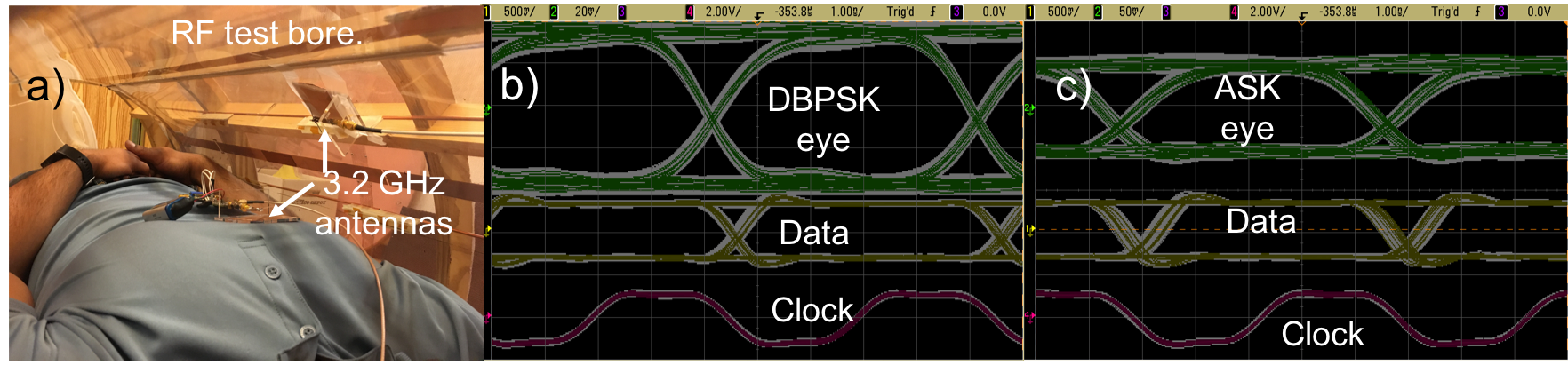
Mock MRI bore wireless transmission test. a) A test subject lies in the bore with a 3.2 GHz antenna on the chest and a receive antenna at the bore wall. b) DPSK demodulated analog eye waveform and recovered data and clock. The oscilloscope grey traces are infinite persistence to show waveform deviations. c) ASK demodulate analog eye waveform and clock and data recovered signals. The RF signal integrity appears sufficient to support at least 200 Mbps for 10-30cm link distances, which suffices for MRI in-bore data transfer.