0758
Design of an 8-channel transmit array coil using the equivalent circuit model of the manufactured structure1Electrical and Electronics Engineering Department, Bilkent University, Ankara, Turkey, 2National Magnetic Resonance Research Center (UMRAM), Bilkent University, Ankara, Turkey
Synopsis
We propose a practical approach to designing transmit array (TxArray) precisely by integrating the equivalent circuit model of the manufactured structure and its EM simulation results to reduce the measurements and simulations differences caused by the imperfection in manufacturing. We investigate the performance of a shielded 8-channel degenerate birdcage head TxArray at 123.2MHz together with simulation and experiment to validate the proposed method. All self/mutual-inductances and self/mutual-resistances of the manufactured TxArray have been computed to determine the optimum capacitor values by minimization of the total return power from the coil.
Introduction
Transmit arrays (TxArrays), using multiple parallel RF transmitting elements which provide the additional degrees of freedom, are extensively examined to enhance field uniformity1,2, enable RF shimming while intending to mitigate local SAR3,4, increase power efficiency5,6, or execute implant-friendly modes7. However, TxArray’s performance significantly profits from parallel transmit technology when the coupling between individual array elements is low. Therefore, designing TxArrays, due to the coupling issue, is much more complicated than designing conventional coils.A variety of methods for designing TxArrays in simulation environments has been proposed, such as the co-simulation strategy8, which demonstrated excellent performance. This process replaced all lumped-components with equivalent lumped ports, and calculated TxArrays multi-port scattering matrices, to be used for determining the optimal lumped components. However, for those TxArrays that are not machine-manufactured, measurements with a high probability are different from the simulation results; therefore, special attention needs to be paid to include the exact structure of fabricated TxArray in the design process. Co-simulation may also be used in this case, although it requires numerous measurements, especially for TxArrays with large number of transmitting and lumped elements, to obtain the multi-port $$${\bf{S}}$$$-matrices, which are not feasible.
In this work, we aim to assess the feasibility of using the equivalent circuit model of a manufactured TxArray to reduce the measurement and simulation differences by evaluating the performance of simulated and fabricated 8-channel degenerate birdcage TxArray as an efficient coil for imaging at 123.2MHz. We utilized the equivalent circuit model by considering all magnetic and electrical couplings9-11 to introduce a practical method for the determination of fabricated TxArray’s inductance and resistance values.
Methods
We simulated an 8-channel TxArray coil (Figure1a) using the co-simulation strategy8. By adjusting the capacitors placed between the nearest neighbors, TxArray’s transmit channels could be decoupled. In the design process, the capacitors were adjusted to minimize the following cost function11,12:$$\begin{array}{*{20}{c}}{\begin{array}{*{20}{c}}{\min}&{\frac{1}{8}\sum\limits_{i=1}^8{\sum\limits_{j=1}^8{|{s_{ij}}{|^2}}}+{{\left.{\frac{{P_r^T}}{{P_i^T}}}\right|}_{{\rm{in}}\,{\rm{CP}}\,{\rm{mode}}}}}\end{array}}&{(1)}\end{array}$$
Where $$$P_i^T$$$ and $$$P_r^T$$$indicate the total incident and reflected power from the coil. Furthermore,$$$\sum\limits_{j=1}^8{|{s_{ij}}{|^2}}$$$ can be interpreted as the total reflected to incident power ratio when only one single-channel (SC) is excited. Therefore, Eq.$$$1$$$ intends to minimize the return power for the circularly-polarized (CP) and SC excitation modes as two critical modes of operation. However, the structure of the TxArray supported by two cylindrical plexiglasses (Figure1b) with the capacitors achieved from the simulation was then constructed. As TxArray was not machine-manufactured and therefore not quite the same as the simulated TxArray, we expect that the $$${\bf{S}}$$$-matrices that were simulated or measured would not be the same.
Figure2 illustrates the manufactured TxArray’s equivalent circuit model, which used to provide an efficient and practical strategy in order to determine the suitable capacitors for the fabricated TxArray. The effects of all self/mutual-inductances and self/mutual-resistances13 emanating from the coil, the shield, and the load were taken into consideration.
Based on the model, TxArray impedance matrix, which can simply be derived as a function of the free parameters (capacitors) and frequency ($$$\omega$$$), by analyzing the model with Kirchhoff mesh current method, can be described as follows:
$$\begin{array}{*{20}{c}}{{\bf{Z}}(\omega)=\frac{1}{{j\omega }}({{\bf{C}}_{\bf{m}}}+2{{\bf{C}}_{\bf{s}}})+\frac{1}{{{\omega^2}}}{{\bf{C}}_{\bf{m}}}{{\left({j\omega {\bf{L}}+\frac{1}{{j\omega}}{\bf{C}}+{\bf{R}}}\right)}^{-1}}{{\bf{C}}_{\bf{m}}}}&{(2)}\end{array}$$
where $$${\bf{L}}={\left[{{{\rm{L}}_{{\rm{qp}}}}}\right]_{8\times8}}$$$($$${\bf{L}}={\left[{{{\rm{R}}_{{\rm{qp}}}}}\right]_{8\times8}}$$$) represents the inductance (resistance) matrix in which $$${{\rm{L}}_{{\rm{qp}}}}$$$($$${{\rm{R}}_{{\rm{qp}}}}$$$) indicates the mutual-inductance (-resistance) between the $$$q$$$th and $$$p$$$th loops.$$${{\rm{L}}_{{\rm{qq}}}}$$$($$${{\rm{R}}_{{\rm{qq}}}}$$$) refers to the self-inductance (-resistance) of the $$$q$$$th loop.$$${\bf{C}}{\rm{=}}{\left[{{{\rm{C}}_{{\rm{qp}}}}}\right]_{8\times8}}$$$ and $$${{\bf{C}}_{\bf{x}}}{\rm{=}}{\left[{{\rm{C}}_{{\rm{qp}}}^{\rm{x}}}\right]_{8\times8}}$$$ also represent the capacitance matrices where $$${{\rm{C}}_{{\rm{qp}}}}$$$ and $$${\rm{C}}_{{\rm{qp}}}^{\rm{x}}$$$ are defined as:
$$\begin{array}{*{20}{c}}{\begin{array}{*{20}{c}}{{{\rm{C}}_{{\rm{qp}}}}=\left\{{\begin{array}{*{20}{c}}{\frac{1}{{c_d^{q-1}}}+\frac{1}{{c_d^q}}+\frac{1}{{c_t^q}}+\frac{1}{{c_m^q}}}&{q=p}\\{-\frac{1}{{c_d^{\min\{q,\,p\}}}}}&{q-p\equiv\pm1\,\,({\rm{mode8}})}\\0&{{\rm{other}}}\end{array}}\right.}&{{\rm{and}}}&{{\rm{C}}_{{\rm{qp}}}^{\rm{x}}=\left\{{\begin{array}{*{20}{c}}{\frac{1}{{c_x^q}}}&{q=p}\\0&{{\rm{other}}}\end{array}}\right.}\end{array}}&{(3)}\end{array}$$
The capacitors provided by the simulation can be considered as initial capacitors. By measuring the $$${\bf{Z}}$$$-matrix of the fabricated TxArray for these initial capacitors, the inductance and resistance matrices can be calculated as:
$$\begin{array}{*{20}{c}}{{\bf{R}}(\omega)={\rm{real}}\{\frac{1}{{{\omega^2}}}{{\bf{C}}_{\bf{m}}}{{\left({{\bf{Z}}(\omega)-\frac{1}{{j\omega}}({{\bf{C}}_{\bf{m}}}+2{{\bf{C}}_{\bf{s}}})}\right)}^{-1}}{{\bf{C}}_{\bf{m}}}\}}&{(4)}\\{{\bf{L}}(\omega)=\frac{1}{\omega}{\rm{imag}}\{\frac{1}{{{\omega^2}}}{{\bf{C}}_{\bf{m}}}{{\left({{\bf{Z}}(\omega)-\frac{1}{{j\omega}}({{\bf{C}}_{\bf{m}}}+2{{\bf{C}}_{\bf{s}}})}\right)}^{-1}}{{\bf{C}}_{\bf{m}}}\}+\frac{1}{{{\omega^2}}}{\bf{C}}}&{(5)}\end{array}$$
Once the inductance and resistance matrices are determined, the new capacitors can be accomplished to minimize the cost function implemented in Eq.$$$1$$$ for the fabricated TxArray. The new $$${\bf{Z}}$$$-matrix which fulfills the design criteria can be then measured by updating the capacitors.
Results
The performance of the simulated and fabricated TxArray both with nearly the same capacitor values is shown in Figure3. The simulated and measured reflection coefficients, the reflected to incident power ratio in the SC/CP modes, and $$${\bf{S}}$$$-matrices are described in this figure. Initially, the structure of TxArray was assumed to be circular-symmetric, resulting in identical mounted capacitors at similar locations in each channel. As expected, the measurements differ with the simulation results, therefore the fabricated TxArray is not completely circular-symmetric.By applying the proposed approach to the fabricated TxArray, new quantities of the capacitors were determined. Figure4 compares the performance of the simulated and fabricated TxArrays with the initial and new capacitors, respectively. In this figure, the simulated and measured reflection coefficients, the reflected to incident power ratio in the SC/CP modes, and $$${\bf{S}}$$$-matrices are represented. Figure4 demonstrates that the measurements were approached to the simulation results by mounting the new capacitors.
In order to clarify the proposed method, Figure5 displays a flowchart demonstrating how an optimum capacitor values can be calculated for the manufactured TxArray
Conclusion
Considering the exact manufactured structure of TxArrays in the design process may reduce the error between the measurements and simulations. We developed a practical approach to designing TxArrays precisely by integrating the equivalent circuit model of the manufactured TxArray and the simulation, and then validated it by constructing an 8-channel TxArray and measuring its performanceAcknowledgements
References
1. Avdievich NI, Hoffmann J, Shajan G, Pfrommer A, Giapitzakis IA, Scheffler K, Henning A. Evaluation of transmit efficiency and SAR for a tight fit transceiver human head phased array at 9.4 T. NMR Biomed. 2017 Feb;30(2).
2. Rietsch SHG, Orzada S, Bitz AK, Gratz M, Ladd ME, Quick HH. Parallel transmit capability of various RF transmit elements and arrays at 7T MRI. Magn Reson Med. 2018 Feb;79(2):1116-1126.
3. Van den Berg CA, Van den Bergen B, Van de Kamer JB, Raaymakers BW, Kroeze H, Bartels LW, Lagendijk JJ. Simultaneous B1+ homogenization and specific absorption rate hotspot suppression using a magnetic resonance phased array transmit coil. Magn Reson Med. 2007 Mar;57(3):577-86.
4. Katscher U, Börnert P. Parallel RF transmission in MRI. NMR Biomed. 2006 May;19(3):393-400.
5. Kozlov M, Turner R. Analysis of RF transmit performance for a 7T dual row multichannel MRI loop array. Conf Proc IEEE Eng Med Biol Soc. 2011;2011:547-53.
6. Guérin B, Gebhardt M, Serano P, Adalsteinsson E, Hamm M, Pfeuffer J, Nistler J, Wald LL. Comparison of simulated parallel transmit body arrays at 3 T using excitation uniformity, global SAR, local SAR, and power efficiency metrics. Magn Reson Med. 2015 Mar;73(3):1137-50.
7. Eryaman Y, Guerin B, Akgun C, Herraiz JL, Martin A, Torrado-Carvajal A, Malpica N, Hernandez-Tamames JA, Schiavi E, Adalsteinsson E, Wald LL. Parallel transmit pulse design for patients with deep brain stimulation implants. Magn Reson Med. 2015 May;73(5):1896-903.
8. Kozlov M, Turner R. Fast MRI coil analysis based on 3-D electromagnetic and RF circuit co-simulation. J Magn Reson. 2009 Sep;200(1):147-52.
9. Sadeghi Tarakameh A, Kazemivalipour E, Demir T, Gundogdu U, Atalar E. Design of a degenerate birdcage radiofrequency transmit array coil for the magnetic resonance imaging using equivalent circuit model”, ESMRMB 2017, 34th Annual Scientific Meeting, No: 316. MAGMA 2017; 30:S300–S301.
10. Kazemivalipour E, Sadeghi-Tarakameh A, Yilmaz U, Acikel V, Sen B, Atalar E. A 12-channel degenerate birdcage body transmit array coil for 1.5T MRI scanners. In Proceeding of the 26th Joint Annual Meeting ISMRM-ESMRMB, 2018.
11. Kazemivalipour E, Sadeghi-Tarakameh A, Atalar E. Optimization of the degenerate birdcage transmit array coil for minimum coupling. In Proceeding of the 27th Joint Annual Meeting ISMRM, 2019.
12. Kazemivalipour E, Sadeghi-Tarakameh A, Gundogdu U, Atalar E. Design of multi-row multi-channel degenerate birdcage array coil based on minimum total reflection for the single-channel and circularly polarized modes of excitation. In Proceeding of the 27th Joint Annual Meeting ISMRM, 2019.
13.
Harpen MD. Equivalent circuit for birdcage resonators. Magn Reson Med. 1993
Feb;29(2):263-8.
Figures
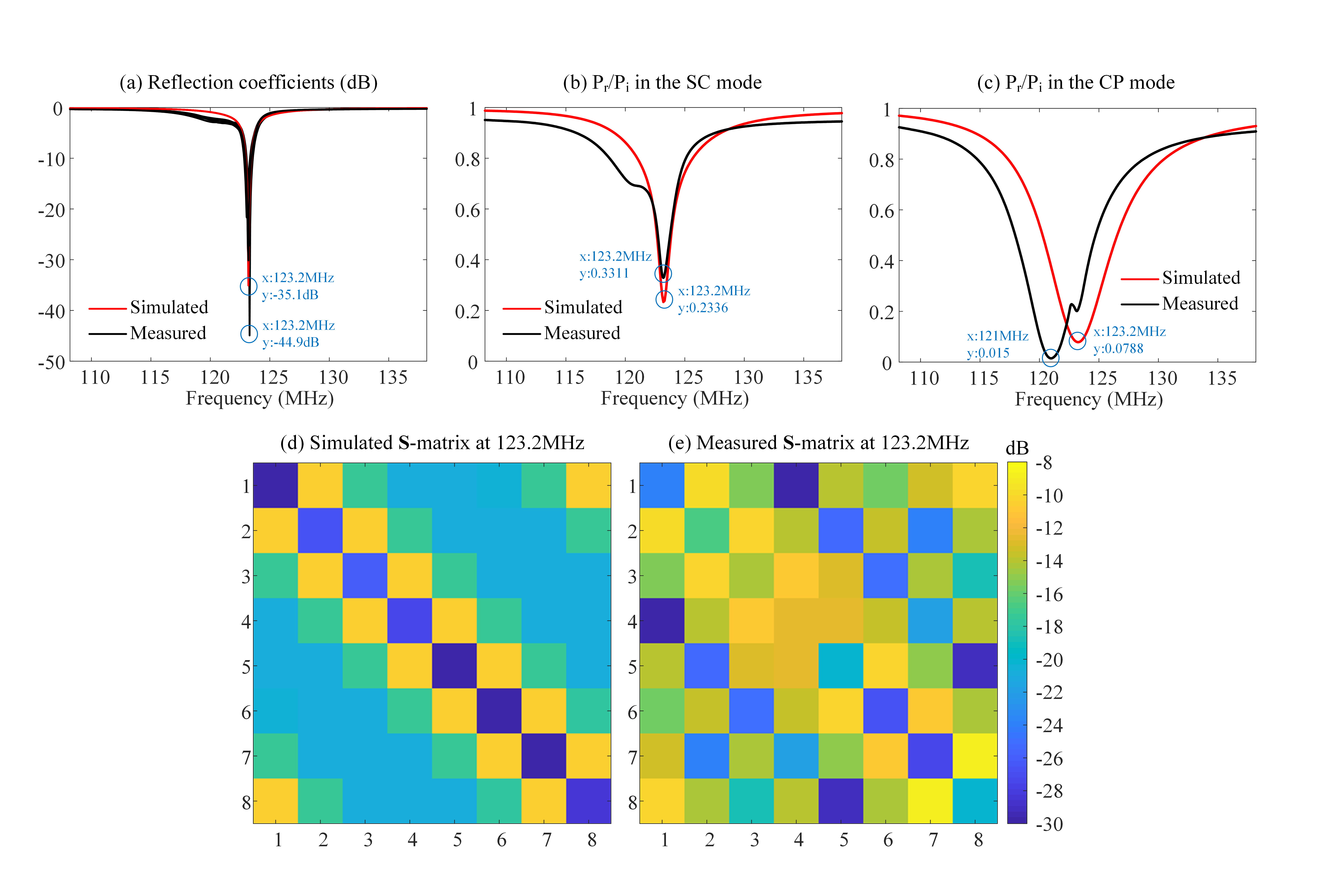
FIGURE4 - Simulated and measured (a) reflection coefficients of 8-channel TxArray and the total reflected to incident power ratio in (b) the SC and (c) CP excitation modes. (d) The simulated and (e) measured $$${\bf{S}}$$$-matrix at 123.2MHz. Simulation results were obtained with the intimal capacitors ($$${c_d}=12.9pF$$$, $$${c_t}=9.5pF$$$, $$${c_m}=34.8pF$$$, and $$${c_s}=10.5pF$$$), while the measurements achieved with the new capacitors ($$${c_d}=14.5\pm0.1pF$$$, $$${c_t}=10.6\pm0.7pF$$$, $$${c_m}=40.4\pm0.2pF$$$, and $$${c_s}=12.9\pm0.1pF$$$)