0757
Optimization of a close-fitting volume RF coil using linear programming for brain imaging at 6.5 mT1State Key Laboratory of Power Transmission Equipment and System Security and New Technology, Chongqing University, Chongqing, China, 2MGH/A.A. Martinos Center for Biomedical Imaging, Cambridge, MA, United States, 3Department of Physics, Harvard University, Cambridge, MA, United States, 4Harvard Medical School, Boston, MA, United States
Synopsis
The use
of a close-fitting roughly head-shaped volume coil for MRI has the merit of
improving the SNR from the brain. However, the surface of
the RF coil follows that of the head, making it difficult to determine the optimal
coil winding pattern. Here, we proposed a method which combines finite element
method simulation and linear programing to optimize the coil pattern of a
close-fitted RF coil with the objective of maximizing its SNR and
RF-magnetic-field homogeneity for operation at ultra-low field (6.5
mT, 276 kHz). We then tested the optimized coil by imaging a
water-filled phantom using a 3D-bSFFP.
Introduction
The use of a close-fitting roughly head-shaped volume coil for MRI has the merit of improving the signal-to-noise ratio (SNR) from the brain. However, the surface of the RF coil follows that of the head, making it difficult to determine the optimal coil winding pattern. Here, we proposed a method which combines finite element method (FEM) simulation and linear programing to optimize the coil pattern of a close-fitted RF coil with the objective of maximizing its SNR and RF-magnetic-field homogeneity for operation at ultra-low magnetic field (6.5 mT, 276 kHz). We then tested the optimized coil pattern by imaging a water-filled phantom using a 3D-bSFFP and we compared the results with the previous spiral RF coil.Method
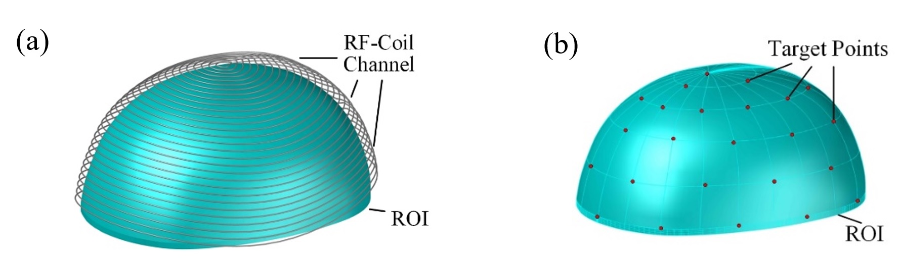
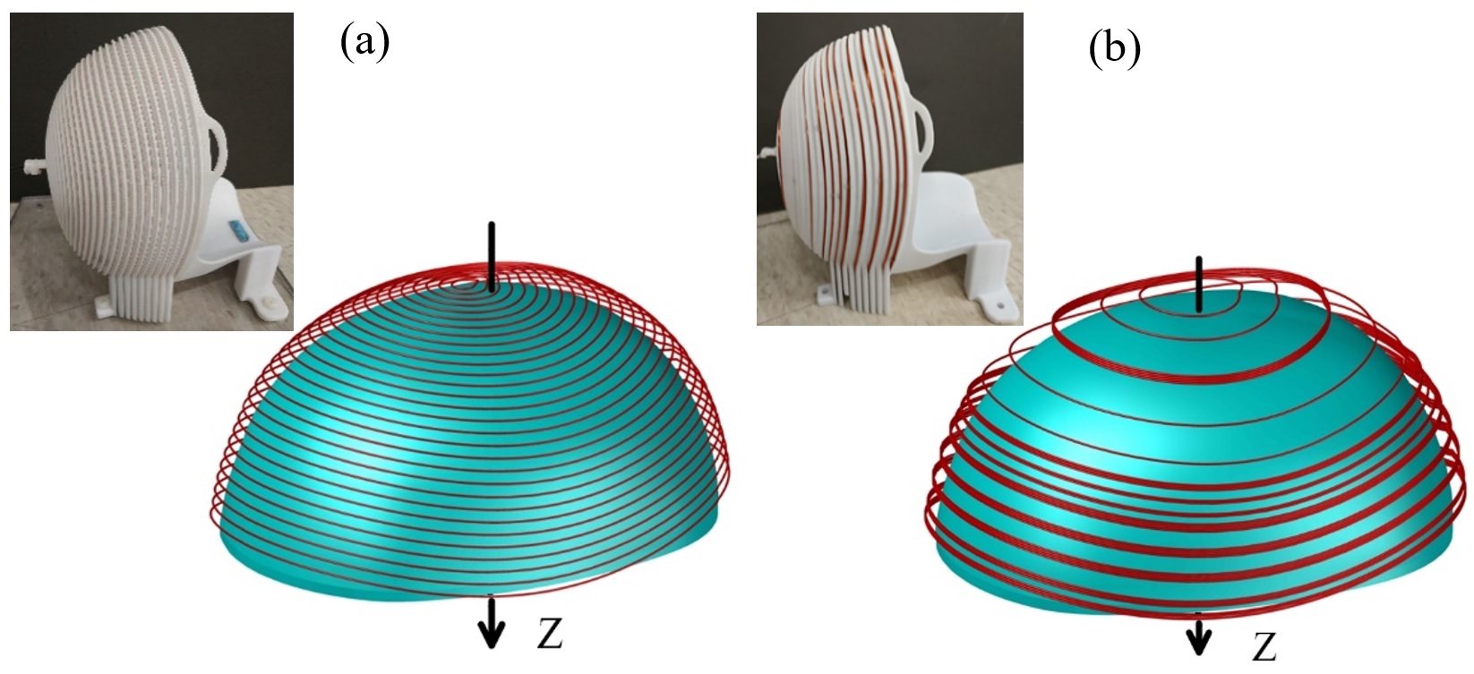
The close-fitting RF coil was wound on a helmet-shaped former, shown as figure 1; an evenly spaced channel for the wire on the helmet was pre-determined, shown as figure 2(a). The region of interest (ROI) whose shape is as same as the brain is seen in blue and the wire channel are overlaid on the ROI. To optimize the pattern of RF coil, first, we need to obtain the magnetic field in ROI generated by each of the wire loops making up the coil. However, the shape of loop is irregular which makes it difficult to deduce a concise analytic expression for magnetic-field calculation. Thus, we introduced FEM to calculate the magnetic field distribution in ROI, generated by the loop at each position with unit current. The index of each loop is m, shown as figure 2(a); the number of target points, we chosen uniformly in ROI, is n, shown as figure 2(b). The magnetic field at each target point was generated by the unit current at all loop locations, denoted by a matrix . The magnetic field in ROI was then calculated by:$$B_{1}=A_{mn}\cdot I_{m}$$ (1)
, where is the vector, which denotes the turns at each location; and each turn was energized by unit current. Besides the magnetic field calculation, we also quantified the performance of RF coil by including it in optimization problem. The performance parameters of RF coil include the SNR, and the homogeneity of RF magnetic field. We demonstrate that the SNR relies on the total length of RF coil, which can be calculated by:
$$L_{total}=L_{m}\cdot I_{m}$$ (2)
, where is the length of each channel in figure 2(a) and can be measured after building the model of the close-fitted helmet. The homogeneity of magnetic field was quantified as:
$$\delta=|\frac{B_{1}-B_{ideal}}{B_{ideal}}|\times100\%$$ (3)
It is the relative error between the ideal RF magnetic field and that generated by the RF coil, where the ideal magnetic field is a constant. Based on the analysis above, we build a linear-programing model which was used to determine the number of the coil turns in each position.
min: $$L_{total}=L_{m}\cdot a_{m}$$
Subject to: $$|\frac{A_{mn}\cdot I_{m}-B_{ideal}}{B_{ideal}}|\times100\%\leq \delta_{0}$$ $$0\leq I_{m} \leq 4 $$ (4)
Imaging
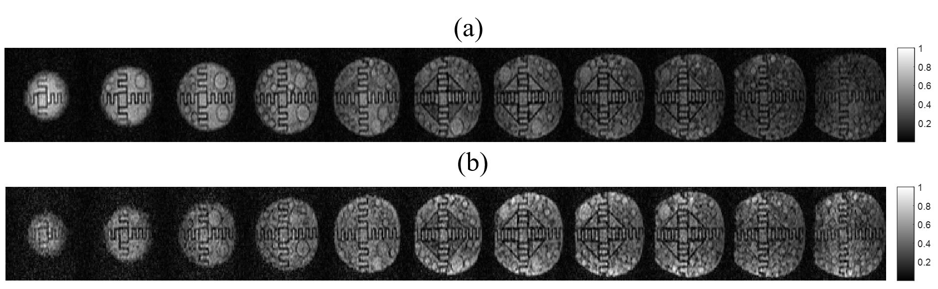
A water-filled structured phantom was placed inside either the optimized RF coil or the spiral RF coil, which was then placed in our ULF MRI scanner, operating at 6.5mT (276kHz). A 3D b-SSFP sequence was used, with the slices in the z direction, a 50% undersampling ratio, matrix size of 75×64×15, voxel size of 2.5×3.5×8.5 mm3, the number of averages of 20 and the scan time was ~4 minutes. The performance of the optimized coil was compared to that of the single channel spiral coil. All the imaging parameters, the receiver gain and shim set values were kept constant. The raw data was then reconstructed by applying the conventional 3D inverse fast Fourier Transform.Results
We obtained an optimal coil with linear programing, shown as figure 3(b), and compared its performance with that of our previous uniformly wound spiral RF coil, shown as figure 3(a). Figure 4 shows the comparison of magnetic field distribution on Z axis. Figure 5 shows the comparison of the imaging result obtained by these 2 coils on a 6.5 mT MRI system which is described in [1].Discussion and Summary
To implement linear programing for RF-coil optimization, we need to set a first. The ,set for the optimal RF coil above, is the average magnetic field generated by spiral RF coil. According to the comparison between spiral RF coil and optimal RF coil, the homogeneity of optimal coil has been improved; the contrast in the images acquired by optimal RF coil is more homogeneous along the z direction than that previous RF spiral coil. A further detailed study of the optimized RF coil would be conducted where the relationship between the initial parameter, , and the performance of RF coil would be evaluated.Acknowledgements
This work was supported by fundings from the National Natural Science Foundation of China (No. 51677008 and 51707028) and the Fundamental Research Funds for the Central Universities (No.2018CDJDDQ0017).
References
[1] M. Sarracanie, C. D. LaPierre, N. Salameh, D. E. J. Waddington, T. Witzel, and M. S. Rosen, “Low-Cost High-Performance MRI,” Sci Rep, vol. 5, no. 1, p. 15177, Oct. 2015.Figures