0756
High impedance coils versus conventional loop coils for transmit purposes: a comparison using an eight channel head coil array for 7 Tesla1Department of radiology, University Medical Center Utrecht, Utrecht, Netherlands, 2Aalto University, Espoo, Finland, 3Biomedical Engineering, Eindhoven University of Technology, Eindhoven, Netherlands
Synopsis
This study compares high impedance coils to conventional loop coils for transmit purposes at 7 Tesla. A new design for high impedance coils is presented. Two eight-channel head arrays of equal dimensions were created; one using high impedance coils, one with conventional loops. B1 field maps are produced to compare transmit efficiency. Scattering parameters are measured in various loading conditions to compare inter-element coupling. The high impedance coils perform worse in terms of transmit efficiency, and better in terms of coupling.
Introduction
At ultrahigh field strengths (≥7T) multi-channel transmit arrays are used to improve B1 field homogeneity. These arrays typically consist of dipole or loop antennas. They are designed to keep the inter-element coupling as low as possible, because strong coupling results in reduced power efficiency in transmission and reduced SNR in reception. Recently a variant of loop coils has been introduced for MRI, named high impedance coil (HIC)1. These loop coils consist of a shielded wire with interruptions in the shield. A voltage applied to the feed port results in a homogeneous current distribution on the outside of the shield, which generates a B1 field similar to a conventional loop coil. They can be constructed out of coax cables to provide flexible coils. Their name stems from the fact that at resonance, the impedance measured at the ports is high (~1 kOhm in loaded condition). This reduces coupling as any mutual impedance between loops becomes smaller in comparison to the high self-impedance. This study aims to compare the performance of these HICs to conventional loop coils in transmission and reception at 7T. Eight-channel head arrays were constructed with both techniques and compared in terms of B1 efficiency and coupling.Design choices
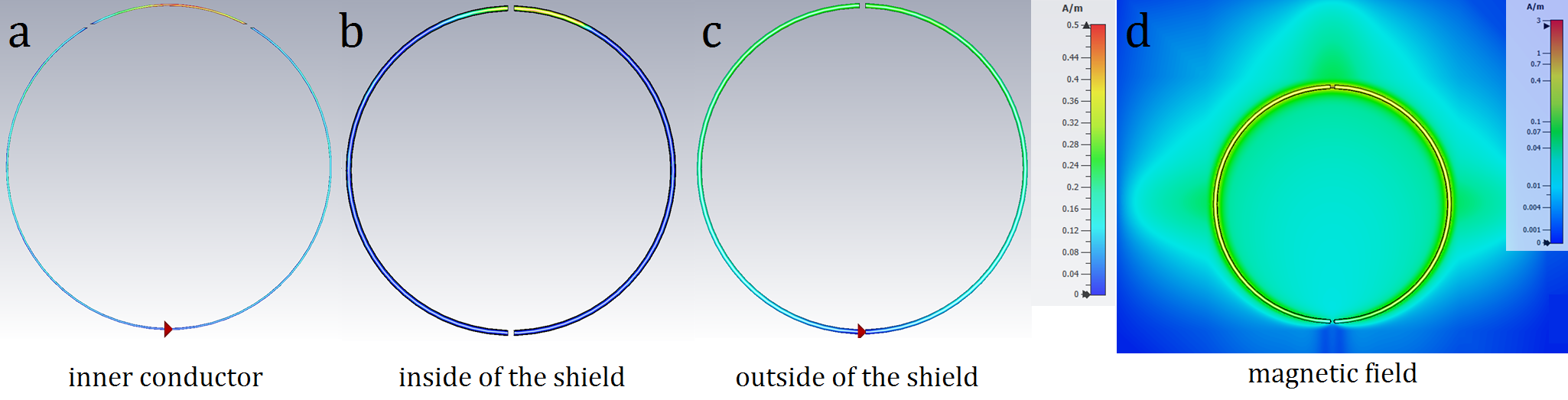
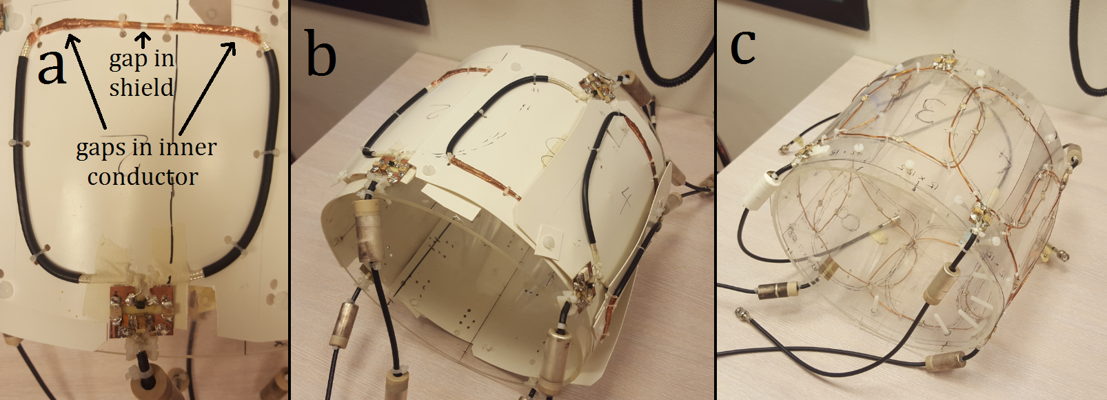
Initial measurements indicated that, just like conventional loops, an array of HICs would require around 10% overlap for optimal decoupling. To build a transmit array with a diameter of 30 cm, this imposes a coil width of approximately 15 cm. Zhang et al.1 describes high impedance coils using only one gap in the inner conductor and shield. The resonance frequency of such coils is determined by the diameter, cable thickness and permittivity of isolating material between inner conductor and shield. At 300 MHz, this approach would yield coils with an impractically small diameter. Ruytenberg et al.2 have demonstrated that ignoring this restriction and tuning a shielded loop coil using a capacitor produces an adequate coil, without the high impedance. Czerny et al.3 demonstrate that by adding more gaps the diameter can be increased while preserving its high input impedance. Using FEM simulations (CST Microwave Studio) a combination of gaps was found which resulted in HICs with a high impedance of 20 kOhm in unloaded situation at 300 MHz (figure 1). However, this did result in a slightly asymmetric current distribution on the outside of the shield, where the current was strongest opposite to the port. During construction it was found that better decoupling could be achieved by positioning each coil in opposite orientation with respect to its neighbours. (figure 2) To maintain optimal overlap, the last two coils were constructed wider than the rest (17cm). For a fair comparison, these design choices were repeated in the array of conventional loops.Methods
Eight high-impedance loops (width/height: 15-17/15cm) were constructed from coax cables and copper foil. The loops were tuned by interrupting the inner and outer conductor by gaps (figure 1) and matched to 50 Ohms. Eight conventional loop coils with the same dimensions were made from copper wire and tuned using capacitors. Each set of eight loops was positioned on a cylindrical tube (diameter 30cm) and overlapped for optimal decoupling. B1 maps were created using parallel transmission with phase shimming on a 7T scanner (Philips Achieva). Scattering parameters were measured using directional couplers. Three phantoms were used to test different loading conditions: A strongly loading salt water bottle (diameter/length 15cm/25cm), a moderately loading spherical phantom (diameter 10cm), and a weakly loading oil phantom. A commercial 8-channel transmit array (Nova Medical) was used for reference.Results
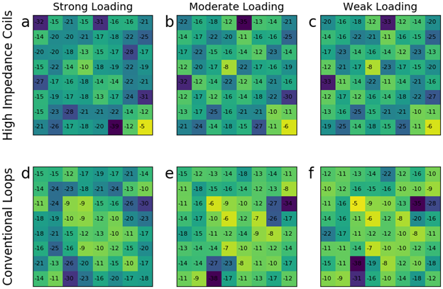
During construction it was notably easier to decouple the HICs using overlap. With the conventional loop coils, shifting the coil by a few millimeters could result in 5 to 10 dB change in coupling and/or matching. This resulted in a very tedious construction process. With the HICs construction was much easier; Due to their flexible design, the overlap could easily be adjusted without significantly affecting the matching.Figure 3 shows B1+maps acquired using the moderately loading phantom. The HICs generate 20% less B1 than the conventional loops, when normalised to forward power. When normalised to accepted power, the HICs generate 32% less B1. Figure 4 shows scattering matrices for both arrays when loaded with different phantoms. The HICs are seen to have lower coupling than the conventional loops. In each loading situation the strongest inter-element coupling was around 4 dB lower for the HICs.
Discussion
Results have shown that the HICs have lower B1 efficiency than conventional loops. This is in contrast to results by Ruytenberg et al.2 who finds similar B1 at depth when comparing shielded-coaxial-cable coils (similar to our HICs, but smaller and with fewer gaps) to conventional loops. One possible explanation is the fact that the gap positions used to tune the high impedance of the coil result in a slightly asymmetric current pattern on the outer conductor. The lower coupling values are in agreement with results reported by others1,2. Future studies will focus on improving the B1 efficiency by optimizing the number and locations of the gaps to provide a more homogeneous current distribution over the outer conductor.Acknowledgements
No acknowledgement found.References
1. Zhang, B., Sodickson, D. K., & Cloos, M. A. (2018). A high-impedance detector-array glove for magnetic resonance imaging of the hand. Nature biomedical engineering, 2(8), 570–577. doi:10.1038/s41551-018-0233-y
2. Ruytenberg, T, Webb, A, Zivkovic, I. Shielded‐coaxial‐cable coils as receive and transceive array elements for 7T human MRI. Magn Reson Med. 2019; 00: 1– 12. https://doi.org/10.1002/mrm.27964
3. Czerny, Raphaela & Nohava, Lena & Frass-Kriegl, Roberta & Felblinger, Jacques & Ginefri, J.-C & Laistler, Elmar. (2019). Flexible multi-turn multi-gap coaxial RF coils: enabling a large range of coil sizes. Proc. ISMRM 2019, #1550
Figures