0753
A 22-channel high impedance glove array for dynamic hand and wrist imaging at 3T1Center for Advanced Imaging Innovation and Research, New York University School of Medicine, New York, NY, United States, 2Advanced Imaging Research Center, University of Texas Southwestern Medical Center, Dallas, TX, United States, 3The Sackler Institute of Graduate Biomedical Sciences, New York University School of Medicine, New York, NY, United States, 4Siemens Healthcare, Erlangen, Germany
Synopsis
We constructed a 22-channel high impedance glove array for dynamic hand and wrist imaging. The glove array has a robust, flexible, comfortable, safe, and cleanable construction. Siemens Tim4G technology was used to connect coils to the scanner through a single bundled cable to streamline the workflow and permit hand postures that are uninhibited by bulky components. Compared to a rigid commercial 16-channel Hand/Wrist coil, our 22-channel glove array showed higher SNR on fingers and wrist and comparable SNR on the palm and top of the hand. Further analysis revealed low coupling between the coils that resulted in good acceleration performance.
Introduction
Our recently introduced high-impedance coil (HIC) technology enables wearable phased arrays that can adapt to the subject’s anatomy and accommodate dynamic imaging, as was illustrated using a prototype 8-channel glove coil [1]. However, further experiments revealed that the delicate pre-fabricated glove substrate could not withstand the wear and tear of routine use. In addition, the limited number of coil elements did not provide extensive coverage of the wrist. In this work, we redesigned the HIC glove coil from the ground up using a custom-made glove with specially designed features to embed the electronics and greatly enhance robustness such that it can be used routinely. In addition, the number of coil elements was increased from 8 to 22.Method
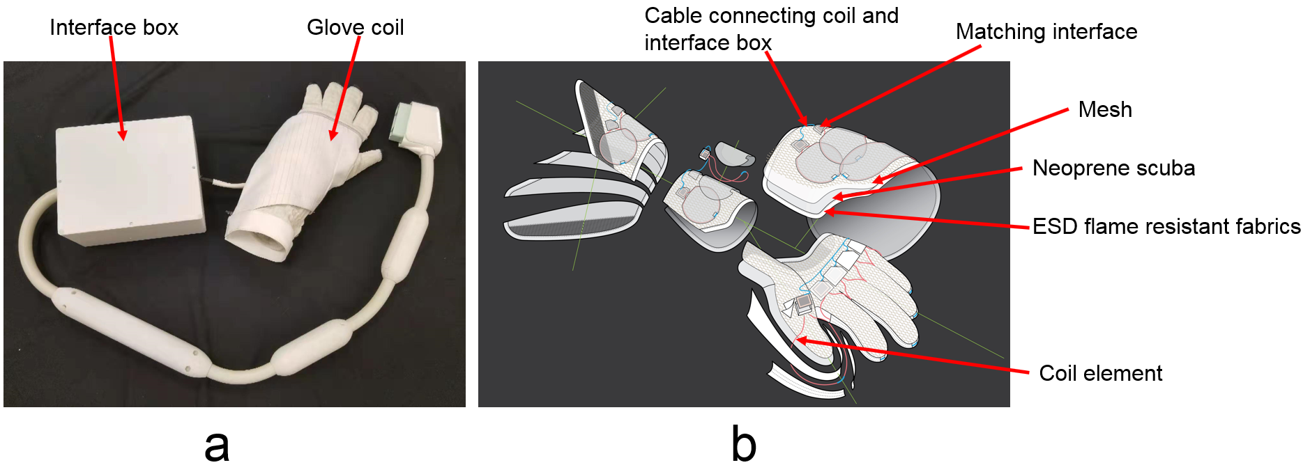
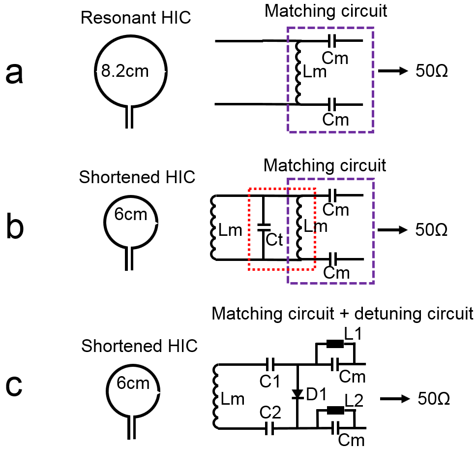
Figure 1 shows a picture of the completed 22-channel glove array prototype and an exploded view of the design. The lightweight and flexible micro-coaxial cable coil elements (∅ = 6cm) were inserted into dedicated tubes sewn into the fabric. The inner glove itself consisted of four main structures: palm, fingers, wrist and a flap that rolls over on top. Each structure was constructed out of three layers, an ESD flame resistant inner layer for safety, with an elastic layer on top (neoprene scuba), covered by a mesh fabric to help organize the cables connecting the coils to the interface box. The overlap between the coils varied with the size and posture of the subject’s hand. In order to remove the bulky inductor from the matching interface shown in Figure 2a, the HIC was deliberately shortened to have a residual inductance Lm at the Larmor frequency (Figure 2b). In this condition, a tuning capacitor (Ct) could be used to form a parallel resonant circuit with Lm, which eliminated Lm and Ct from the interface board. To ensure adequate DC bias for active detuning during transmit, we further redesigned the interface board (Figure 2c) to use only one PIN diode (D1) instead of two for detuning. A fuse was added in each coil to provide redundant protection in the event of an active detuning failure. The dimension of the entire matching interface is 15mm×20mm×6.5mm. The output from the matching interface was connected to the preamplifiers. Lumped phase shifters were used to achieve “reversed” preamplifier decoupling for all the coil elements [1], and cable traps were added to suppress shield currents. The Siemens Tim4G technology was used to connect all 22 coils to the scanner through a single plug to streamline the workflow and permit hand postures that are uninhibited by bulky, cumbersome components. An outer glove was used to cover the exposed electronics. The outer glove was made of pleats covering the fingers to allow movement and neoprene scuba covering the other area.After safety test on a hand-shaped phantom, a healthy volunteer was scanned (with institutional IRB approval) to compare the SNR of the new glove array to a commercially available rigid 16-channel Hand/Wrist array (Siemens, Erlangen, Germany). SNR maps were reconstructed with optimal coil combination from two GRE sequences with and without RF excitation (FOV 384mm×192mm , matrix 512×256 , TR 200 ms, TE 3.0 ms, flip angle 25°) [2], and inverse g-factor maps were synthetically generated from the fully sampled data [3]. High resolution (250um×250um) T1-weighted turbo spin echo (TSE) images of the left hand were acquired in the coronal plane (matrix 1024×1024, FOV 256x192mm, Turbo factor 2, excitation/refocusing angle 90°/180°, TR 400ms, TE 15ms). All scans were performed on a MAGNETOM Skyra 3T MRI system (Siemens Healthcare, Erlangen, Germany).
Result & Discussion
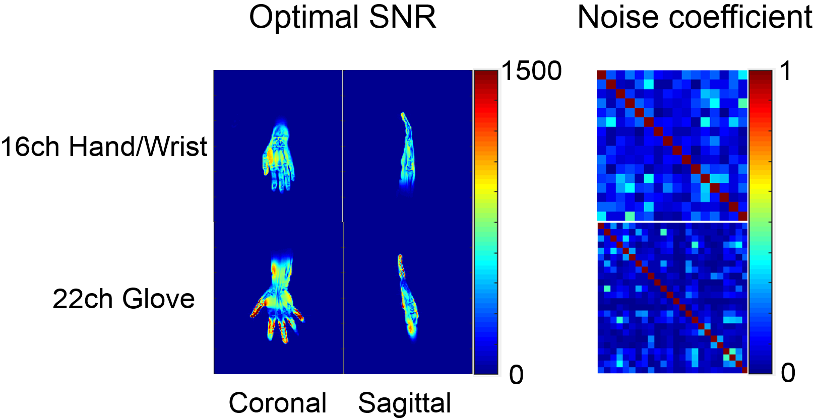
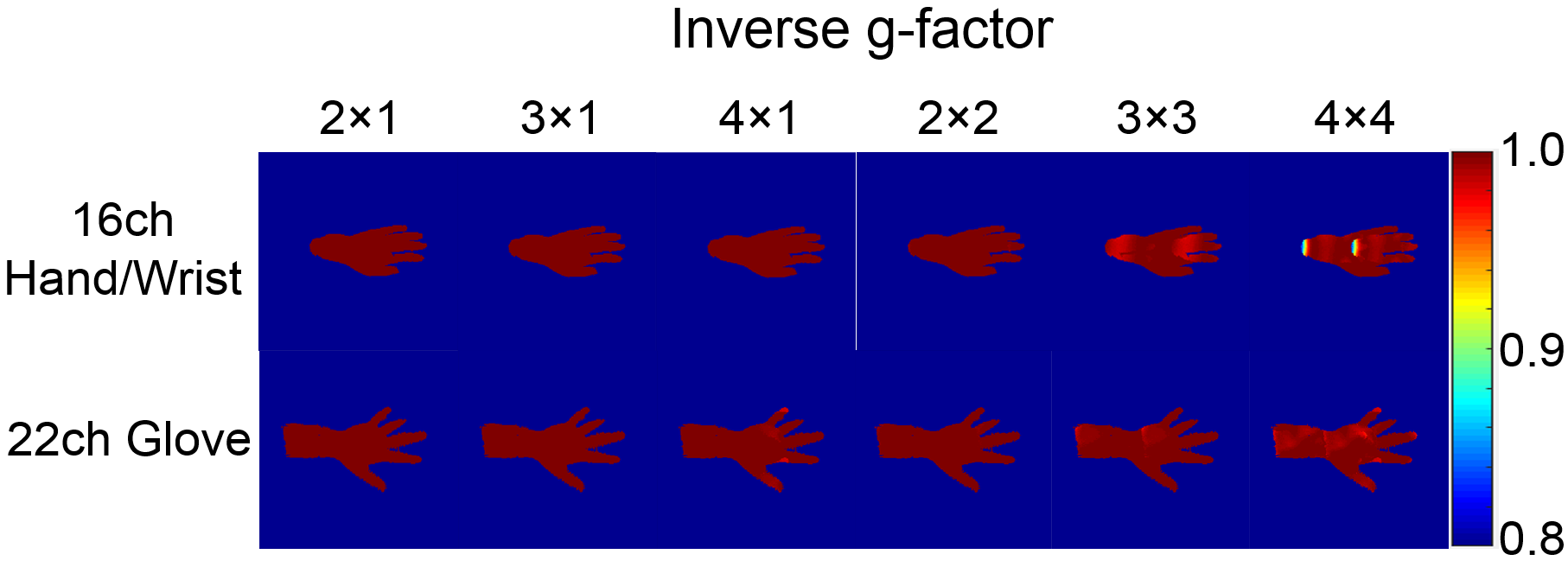
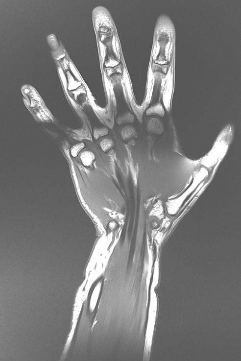
Figure 3 compares the optimal SNR in coronal and sagittal planes, as well as the noise coefficient matrices, for the 16-channel Hand/Wrist array and the 22-channel glove array prototype. Compared to the commercially available coil, our glove array demonstrated overall 63% higher SNR in fingers. In the palm and top of the hand their performance was about equal (98%), whereas in wrist our glove was again 33% better. The mean value of the noise coefficient matrix was 0.118 for our glove array and 0.192 for the Hand/Wrist array. Looking at the inverse g-factor maps shown in Figure 4, by increasing coil elements from 8 to 22, our glove array shows excellent acceleration performance, with less than 10% g-factor penalty for 16x acceleration (4 by 4). From the high-resolution TSE image in Figure 5, we can see that the coil has excellent coverage of hand and wrist, enabling dynamic imaging in this anatomy [4]. However, there is small gap in the coverage at the metacarpophalangeal joints (knuckle), where the top row of coils on the central flap (marked in figure 1) and finger coils meet. To mitigate this problem, we will try to add one coil over the knuckles.Conclusion
Our 22-channel high impedance glove array prototype achieved higher SNR in the fingers and wrist, and comparable SNR on the palm and top of the hand, when compared with a commercial 16-channel Hand/Wrist coil. Unlike the fragile pre-fabricated glove that we used in our first prototype, our tailor-made glove housing enhanced flexibility, comfort, robustness and cleanability of the array, enabling it to be used routinely for dynamic or static hand and wrist imaging.Acknowledgements
This work was performed under the rubric of the Center for Advanced Imaging Innovation and Research (CAI2R, www.cai2r.net) at the New York University School of Medicine, which is an NIBIB Biomedical Technology Resource Center (NIH P41 EB017183).References
1. Zhang B, Sodickson DK, Cloos MA. A high-impedance detector-array glove for magnetic resonance imaging of the hand. Nat Biomed Eng. 2018. doi: 10.1038/s41551-018-0233-y.
2. Kellman P, McVeigh ER. Image reconstruction in SNR units: a general method for SNR measurement. Magn Reson Med 2005;54(6):1439-1447
3. Pruessmann KP, Weiger M, Scheidegger MB, Boesiger P. SENSE: sensitivity encoding for fast MRI. Magn Reson Med. 1999;42(5):952-62. PubMed PMID: 10542355
4. Abbas B, Fishbaugh J, Petchprapa C, Lattanzi R, Gerig G. Analysis of the kinematic motion of the wrist from 4D magnetic resonance imaging, Proceedings Volume 10949, Medical Imaging 2019: Image Processing; 109491E (2019)
Figures