0752
Shielding Effects on Signal-to-Noise Ratio at Ultra-High Field MRI1Center for Advanced Imaging Innovation and Research, New York University School of Medicine, New York, NY, United States, 2Advanced Imaging Research Center, University of Texas Southwestern Medical Center, Dallas, TX, United States, 3Center for Magnetic Resonance Research, University of Minnesota, Minneapolis, MN, United States, 4Stanford University, Stanford, CA, United States, 5The Sackler Institute of Graduate Biomedical Sciences, New York University School of Medicine, New York, NY, United States
Synopsis
We evaluated the effect of a radio frequency shield on the signal-to-noise ratio (SNR) of a loop coil at various field strengths in simulation. At 7T, SNR constantly improves as the shield diameter increases. At higher field strengths, SNR is maximized when using an optimal shield diameter, which is inversely proportional to the frequency. We also show that central SNR for a 32-channel receive array could drop by a factor of two when using a non-optimal shield diameter at 10.5T. Inserting a transmit array between the receiver and an optimally-sized shield could considerably deteriorate SNR.
Introduction
In ultra-high field (UHF) MRI systems, a radiofrequency (RF) shield can reduce radiative power losses of RF coils, behave as a waveguide for traveling waves [1], and also affect the interactions of the RF field with the subject, because it defines the scattering boundary conditions. The effects of shielding on RF coil performance depend on the size of the RF shield relative to the RF wavelength [2]. Although these effects are expected to be large at ultra-high field MRI, they have not been explored thoroughly so far. In this work, we used full-wave simulations to evaluate the effect of RF shield size on signal-to-noise ratio (SNR) at various magnetic field strengths.METHOD
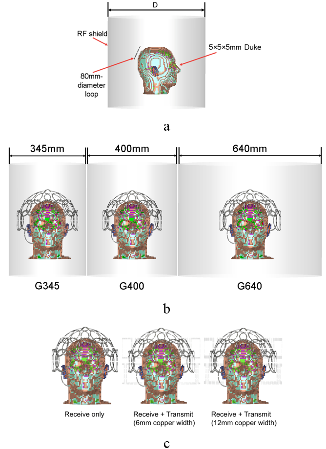
We used CST microwave studio (Computer Simulation Technology, CST, Darmstadt, Germany) to calculate the SNR of an 80mm-diameter loop coil located at the back of a 5mm×5mm×5mm human head model (Figure 1a). We performed the calculations at 7T, 9T, 10.5T, 11.7T and 14T for different diameters (345mm, 365mm, 385mm, then from 400mm to 640mm with 20mm step) of the RF shield. To further explore the effect of the shield size on SNR due to the wavelength, we extended the 14T simulations to 305mm~920mm-diameter RF shield. Then we repeated the same simulations after lifting the RF coil by 20mm, excluding the case of 305mm-diameter shield since it was too small to enclose the RF coil. In all the above simulations, conductive material was modeled as perfect electric conductor. We also repeated the 10.5T simulations using a conductivity of 3.8×10⁵ S/m for the shield, which is approximately two order of magnitude lower than for copper and could be achieved in practice. Based on the results for the loop, we calculated the SNR of a 10.5T 32-channel head array for three shield diameters: 345mm, 400mm and 640mm (Figure 1b). At last, we tested whether the detuned copper conductors of a 15channel transmit array (shown in setup 1 in [3]) would act as a shield and affect the SNR of the 32-channel receiver, using two widths for the transmit array conductors (Figure 1c). Coils were tuned and matched in co-simulation for each simulation. For the single coil simulations, we averaged the SNR over all voxels of the human head model to compute an overall SNR value.RESULT
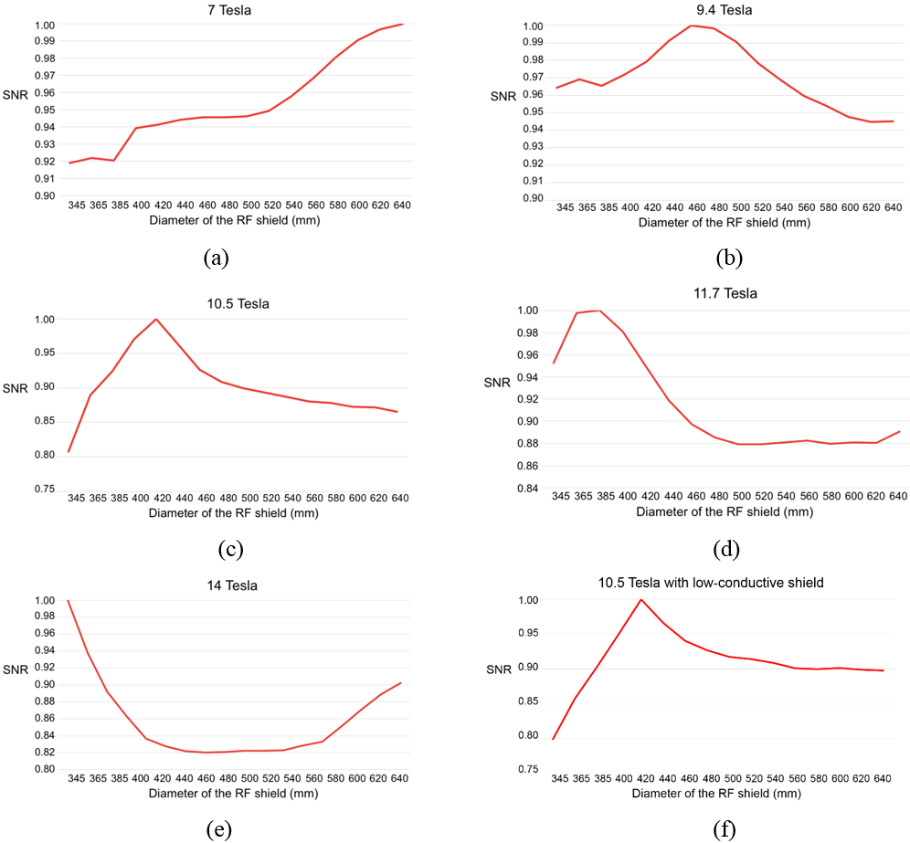
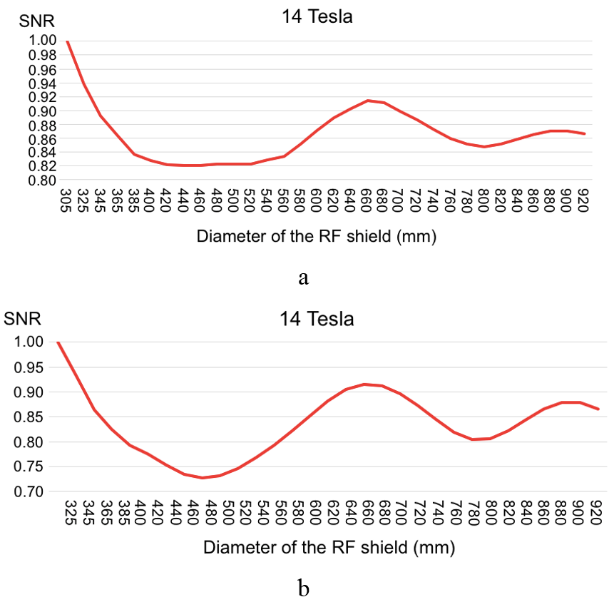
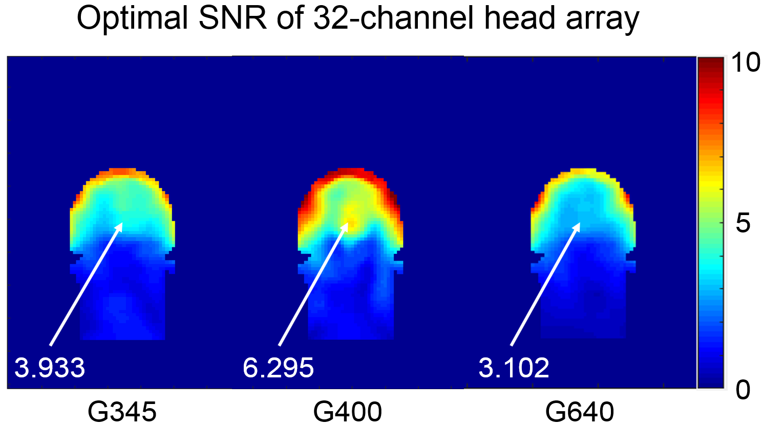
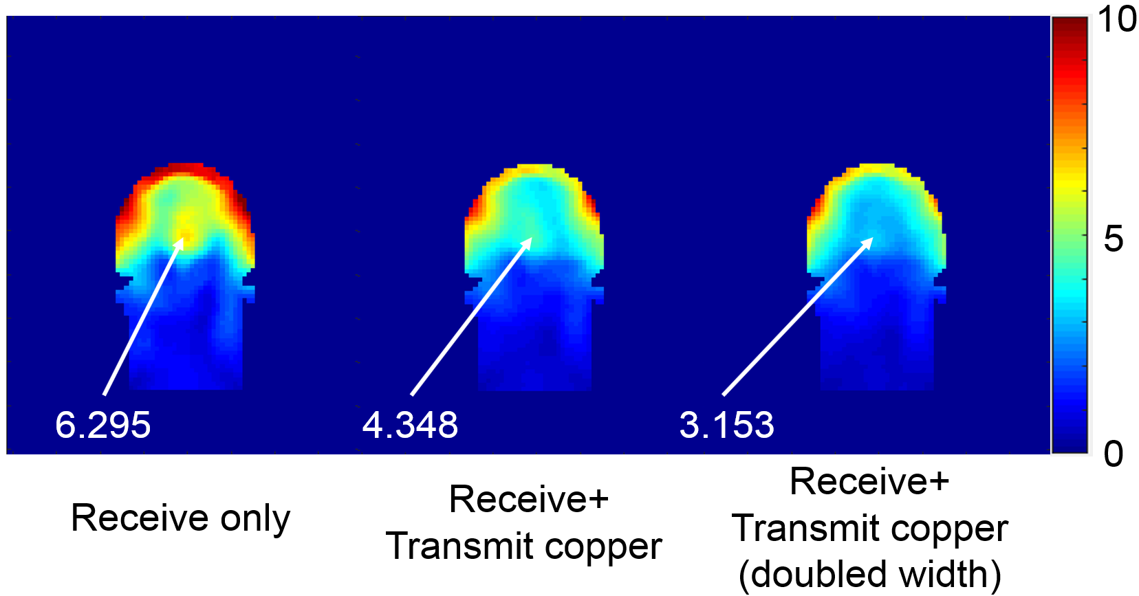
Figure 2 shows that the SNR monotonically increased with shield diameter at 7T; the SNR reached a peak with the ~465mm-diameter shield and was lower by as much as 6% for other diameters at 9.4T; the optimal diameter was ~420mm at 10.5T, for both the high and low-conductivity shield, with the SNR decreasing as much as 20% when the shield was close to the coil; A smaller diameter (~378mm) was instead optimal at 11.7T, while the SNR decreased rapidly by 12% at larger diameters; at 14T, the SNR was maximum with the shield close to the RF coil (345mm diameter), then decreased by ~20% between 440mm and 540mm, and seemed to grow again for larger diameters. We further investigated that in Figure 3a for diameters between 305mm and 920mm, showing that the SNR is the highest when the shield is just above the coil, and its value fluctuates as the diameter of the RF shield increased. After lifting the coil by 20mm, the relationship between SNR and shield diameter resembled more closely the Bessel function of the first kind (Figure 3b), with the first minimum corresponding to ~27% SNR loss. The 32-channel head array simulations at 10.5T confirmed that shielding effects could change SNR considerably. Using a shield diameter similar to the optimal one predicted by the single coil simulations, central SNR was 1.6 and 2 times higher than for a smaller (345mm) and larger (640mm) diameter, respectively (Figure 4). Moreover, the interference pattern resulting from the 400mm-diameter shield created a SNR hotspot at the center of the head. Figure 5 shows that the detuned elements of a transmit array inserted between the receive array and the optimally-sized RF shield induced additional shielding effects, which reduced central SNR by 31%, when the copper width of the transmit elements was 6mm, and 49% when the copper width was doubled.DISCUSSION AND CONCLUSION
The SNR-optimal shield diameter was approximately 470mm and 420mm at 9.4T and 10.5T, respectively. The ratio of the two optimal diameters is 1.12, which is consistent with the ratio of the corresponding resonant frequencies (447.06/400=1.12). This suggests that the optimal shield diameter would be approximately 377mm at 11.7T and 307.5mm at 14T, which is consistent with the results shown in Figure 2d and 2e. RF shields are unavoidable, especially when using head gradients inserts, and our results showed that they should be carefully designed to avoid compromising the SNR advantage of UHF MRI. Since an external transmit array between the receiver and the shield might deteriorate SNR, transmit-receive arrangements or external transmit arrays with a smaller copper footprint (e.g., dipoles) should be considered. Our future work will include building an experiment setup at 10.5T to evaluate the shielding effects on SNR when surrounding the receive array with a transmit array, using the optimal shield diameter.Acknowledgements
This work was supported in part by NIH U01 EB025144, NIH R01 EB024536, NSF 1453675, and was performed under the rubric of the Center for Advanced Imaging Innovation and Research (CAI2R, www.cai2r.net) and CMRR, NIBIB Biomedical Technology Resource Centers (NIH P41 EB017183 and P41 EB015894).References
1. Brunner DO, Zanche ND, Frohlich J, Paska J, Pruessmann KP. Travelling-wave nuclear magnetic resonance. Nature 2009; 457:994–999
2. Ong KC, Wen H, Chesnick AS, Duewell S, Jaffer FA, Balaban RS. Radiofrequency shielding of surface coils at 4.0 T. J Magn Reson Imaging. 1995 Nov-Dec;5(6):773-7
3. Zhang B, Collins C, Galore R, Jungst S, Grant A, Ugurbil K, Adriany G, Lattanzi R. A comparison of the transmit efficiency of loops vs. dipoles for a 16-channels head array using different RF shims at 10.5 T. ISMRM Workshop on Ultrahigh Field Magnetic Resonance: Technological Advances, Translational Research Promises & Clinical Applications, 2019
Figures