0751
Practical eight-channel pTx system for 7 T MRI with optically controlled and monitored on-coil current-source RF amplifiers
Natalia Gudino1, Jacco A de Zwart1, and Jeff H Duyn1
1LFMI, NINDS, National Institutes of Health, Bethesda, MD, United States
1LFMI, NINDS, National Institutes of Health, Bethesda, MD, United States
Synopsis
We present an eight channel pTx-Rx system built with optically controlled and monitored on-coil Tx amplifiers and optical pTx control optimized for 7 T imaging. We show preliminary results of the technology implemented for human head imaging.
Introduction
Optically controlled and monitored on-coil current-mode RF transmit amplifiers are ideally suited to practically implement parallel transmit (pTx) systems at high and ultra-high field1-3. We present an eight-channel pTx system built around an optimized 300 MHz optically controlled on-coil amplifier prototype3. Preliminary tests were performed to assess the performance of this technology for human head imaging at 7 T.Methods
An 8-channel pTx system was built with on-coil current-source RF power amplifiers (RFPA) that were further developed from previous work3. In the new design, each amplifier (Fig. 1a) received four optical signals: encoded RF envelope and carrier; sync (CS) and clock (SCLK) signals. A passive mixer (pSemi PE4141) was implemented to down-convert the RF current sensed at the amplifier output. All monitoring electronics were shielded to avoid degradation of the small signal from interference with the high-power RF signal. Coils were operated in combined transmit-receive mode. Amplifiers were controlled by an eight channel in-house built pTx interface based on vector modulation1,4, which generates 8 optical carriers, 8 optical envelopes, 4 CS and 4 SCLK signals transmitted to the amplifier boards for ADC and DAC control through 1:2 or 1:4 optical splitters. The interface was connected to the scanner (Siemens Magnetom 7T) RF small signal (scanner RFPA input), 10 MHz reference clock and RF unblank. This interface also receives the optical down-converted RF coil current sensed in each amplifier, which was sent to a controller (Linux computer) for monitoring and feedback. The controller updated the 16 baseband signals of vector modulators that set amplitudes and phases for each RF pulse. All electronics were assembled in a 2U rackmount box with a commercial switch-mode power supply (5 V, 5 A) (Fig. 1b). For performance testing, each amplifier was connected to a 6 cm diameter loop through a small PCB that contains a Tx-Rx switch and low-noise amplifier (LNA)5 for amplification of the MR signal6. Element decoupling was achieved through the LNA low input impedance and the RFPA high output impedance during signal reception and RF transmission respectively. Coils and electronics were assembled on a 265 mm diameter cylindrical former with a sliding RF shield to reduce interference with the surrounding hardware in the scanner bore (Fig. 1c). On the bench, maximum power delivered to the coil, current and B1 field were measured with a calibrated probe. Transmit decoupling was measured with one channel at B1 amplitude 22 𝜇T, all others at zero. The new RF amplifier was also tested while connected to a larger coil of dimension 120 x 70 mm2 designed such that 8 coils can be geometrically overlapped on the 265 mm diameter cylindrical former. Images of a spherical oil phantom (24 cm diameter) and a phantom simulating brain tissue at 300 MHz7 were acquired using a gradient echo sequence (TR/TE=250/10 ms, FOV= 350 x 350 mm2, matrix size 128 x 128 and slice thickness 5 mm) while the RF transmit current in each loop was monitored in real time. B1+ field distribution was evaluated in the scanner with the larger Tx loop placed 1 cm above a spherical silicon oil phantom with diameter similar to a human head (175 mm). In this setup signal was received with a separate Rx volume coil. A preliminary human study was performed with the new Tx-Rx array under IRB approval. Average power was restricted, by software and hardware, to 1.5 W and amplitude and phase values per channel set for CP excitation.Results
In this new prototype, optical SCLK and CS input to each amplifier controlled on-coil ADC and DAC. Allowing a more stable digital data transmission than in the previous 4-channel implementation3. Lower power dissipation and a 10 dB increase in dynamic range (~45 dB total) of the monitored RF current2,3 was possible through the implementation of passive mixing. Figure 2a shows images of the 240 mm diameter oil phantom reconstructed from the 8 received signals while RF power was transmitted with each channel individually and with all channels simultaneously (center image). Figure 2b shows images of the brain phantom obtained with a forward (top) and reversed (bottom) CP excitation mode. Maximum peak power delivered per amplifier versus bias voltage of the amplifier power stage and Tx decoupling values are shown in Fig. 3. Element decoupling was better than -15 dB and -18 dB during signal transmission an RF reception respectively. Figure 4 shows the B1+ penetration estimated from large flip angle excitation (>3 full cycles) using a 2.2 ms hard pulse while bias voltage of the amplifier power stage was 38 V. B1+ in the center of the phantom was around 9 µT for single channel excitation. Single slice images of the in-vivo brain (without B0 shimming) are shown in Fig. 5.Discussion
Further optimization of the on-coil amplifier facilitated practical implementation of an 8-channel pTx system for 7 T imaging. Because of the amplifier decoupling method and current source amplification the coil array is simply an array of resonant loops. Therefore, the design is flexible to drive different coil geometries as well as other types of RF antennas provided that the load to the amplifier remains below its maximum value (~ 25 Ω).Acknowledgements
Steve Dodd, Joe Murphy-Boesch, Peter van Gelderen and Section on Instrumentation at NIMH, NIHReferences
1- Gudino et al. Magn Reson Med. 2016 76(1):340-9. 2- Gudino et al ISMRM 2017 Abstract 0758. 3- Gudino et al. Magn Reson Med. 2018 79(5):2833-2841. 4- Gudino et al. ISMRM 2014 Abstract 0320. 5-Dodd SJ, et al. ISMRM 2012 (Abstract 437). 6- Gudino et al. ISMRM 2017 Abstract 2672. 7-Duan et al. Med Phys. 2014 41(10):102303.Figures
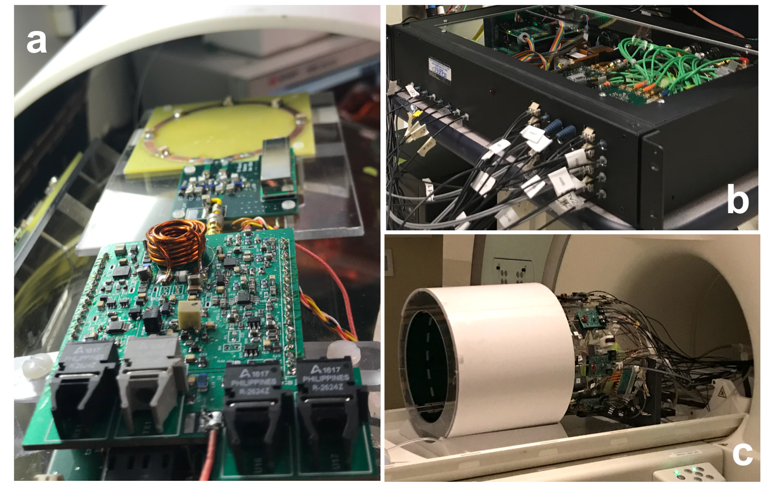
Figure 1: Photos of pTx-Rx hardware (a) 7 T on-coil amplifier with optical control and passive mixing for down conversion of RF sensed current (b) 8-channel optical pTx interface; (c) Optically controlled pTx system in 7 T scanner.
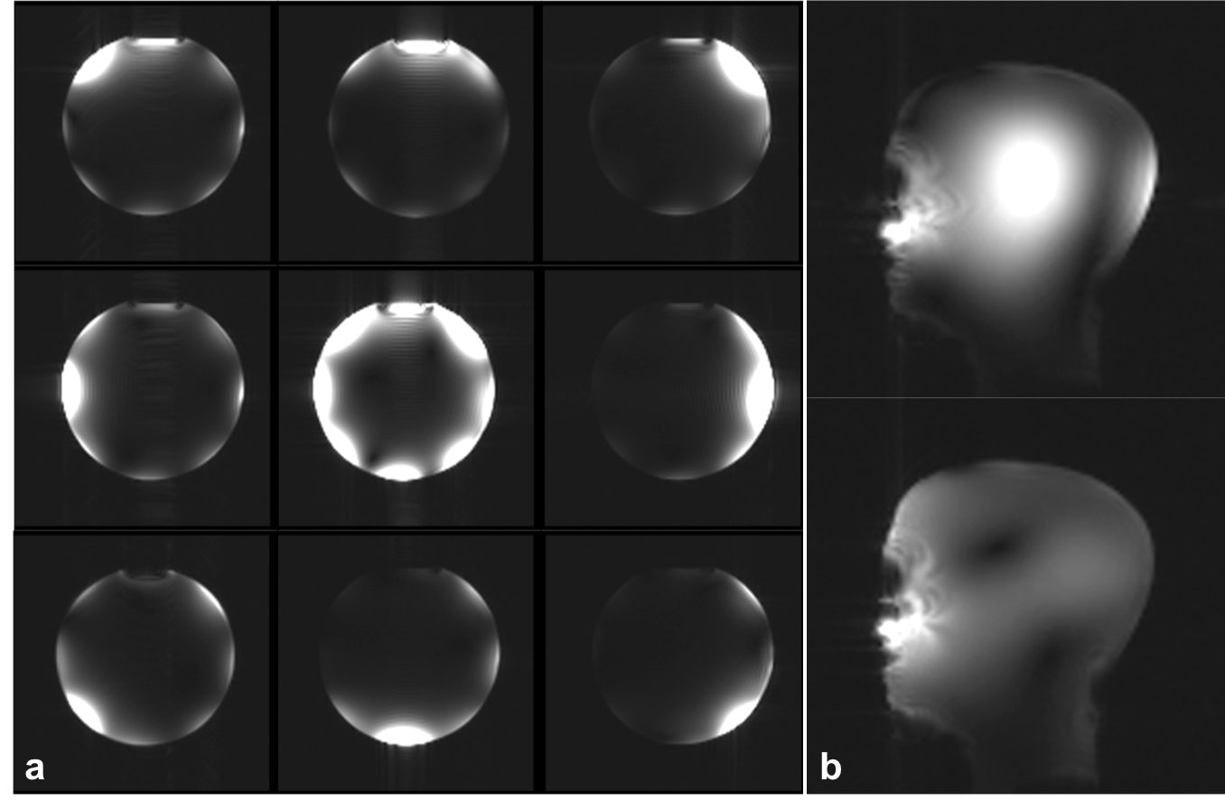
Figure 2: Phantom MRI. (a)
Images of oil phantom obtained while RF power was transmitted with each channel
individually and with all channels simultaneously (center image). (b) Sagittal
slice of brain phantom acquired with a forward and reversed CP Tx mode
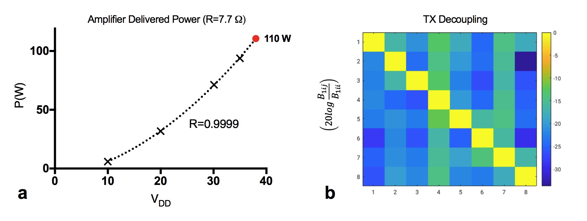
Figure 3: Bechtop Measurements. (a) Peak power delivered to the coil per amplifier. (b) Tx decoupling by amplifier decoupling method.
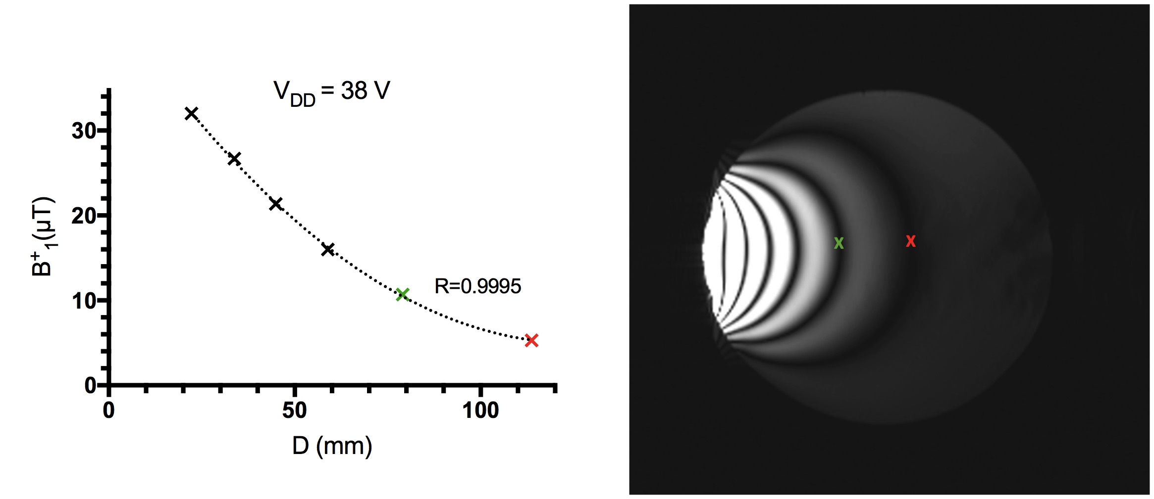
Figure 4: Estimated B1+ field penetration (left) and gradient-echo image (right) obtained with a large flip angle excitation. The amplifier was connected to 120 x 70 mm2 rectangular loop located 1 cm above silicon oil phantom.
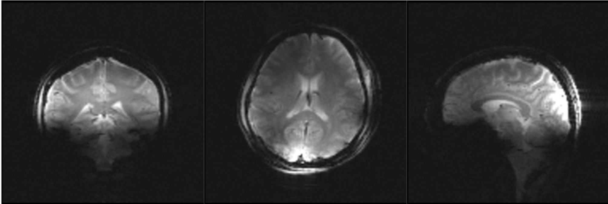
Figure 5: Human brain MRI. Coronal, axial and sagittal images of in-vivo human brain.