0750
Flexible receive-only coaxial coils with multiple turns and gaps for 3 T MRI1IR4M (Imagerie par Résonance Magnétique et Multi-Modalités), UMR8081, Université Paris-Sud/CNRS, Université Paris-Saclay, Orsay, France, 2Division MR Physics, Center for Medical Physics and Biomedical Engineering, Medical University of Vienna, Vienna, Austria, 3Université de Lorraine, Inserm, IADI, Nancy, France
Synopsis
A bench and 3 T MRI study of flexible multi-turn multi-gap coaxial coils and standard copper wire coils with 4, 7, 10 and 15 cm loop diameter is presented. The coaxial coils are made of four different cable types and can be employed for different biomedical applications where form-fitting the coil to the subject anatomy is advantageous. We evaluate the receive-only coaxial coils’ active detuning performance, their robustness upon bending and demonstrate a significant SNR gain when using bent coaxial coils instead of flat standard coils.
Introduction
In clinical 3 T MRI systems, equipped with a transmit body coil, close-fitting and size-optimized1 receive-only RF coil elements are ideal for highly sensitive MR signal detection and often employed in array configuration2. Recently, flexible, lightweight, easy-to-handle receive coils3–6 that can be form-fitted to the anatomy have gained great interest. In this work, we fabricated flexible coaxial coils (CCs) of 4, 7, 10 and 15 cm loop diameter for 1H-imaging at 3 T, following the design principles of multi-turn multi-gap coaxial coils (MTMG-CCs) presented in previous work7–9, allowing for CC size optimization depending on the target anatomical application. We performed bench and MR tests of CCs and standard coils (SCs) with their respective interfaces to investigate SNR performance, test the CCs’ active detuning reliability and CC robustness upon bending.Methods
Coil design and fabrication:Coil diameters were selected to be SNR-optimal for a target penetration depth at different anatomical sites: 4cm (skin, hand, wrist), 7cm (elbow, ankle, breast, head), 10cm (breast, head, knee) and 15cm (abdomen). Suitable CC geometries were calculated using the resonance condition from an equivalent circuit8,9. CC characteristics presented in Table 1 were obtained for a target resonance frequency (fLarmor) of 123.2 MHz within a parameter space given by the variation of number of gaps (ng) in the inner and outer conductor as well as the number of cable turns (nt) and 6 different non-magnetic coaxial cable types. CCs with lowest ng and nt were selected in order to produce lightweight, robust and flexible coils, accepting slight deviations between the desired and calculated frequency (max. ±7%). Furthermore, SCs with the same diameters, segmented by capacitors (segment length ≈λ/20 ), were fabricated of 1 mm copper wire. All fabricated coils and their respective interfacing circuitry at the coil port for tuning, matching and active detuning (AD) during RF transmission are shown in Fig.1a+b.
Bench and MRI measurements:
Fig. 1c depicts a 5l container phantom and a holder set-up including a balloon phantom placed on a Teflon plate used for bench and MRI measurements. Bench tests were performed with all coils directly placed on/under the phantom, SCs and CCs in flat coil position and CCs in half-bent and bent position. S11 measurements (vector network analyzer E5071C, Agilent, Santa Clara, CA, USA) were carried out to determine the loaded resonance frequency (fl) and the matching level (in dB). A decoupled double loop probe10 was used to measure the loaded Q factor. To evaluate SNR performance, GRE MR images in the central transversal slice were acquired on a SIEMENS Prisma Fit 3 T system for the following coil configurations: flat CC and SC, bent CC. To examine the reliability of AD circuits in MTMG-CCs, we performed B1+ mapping with and without the CC present, using the body coil for Tx/Rx.
Results and discussion
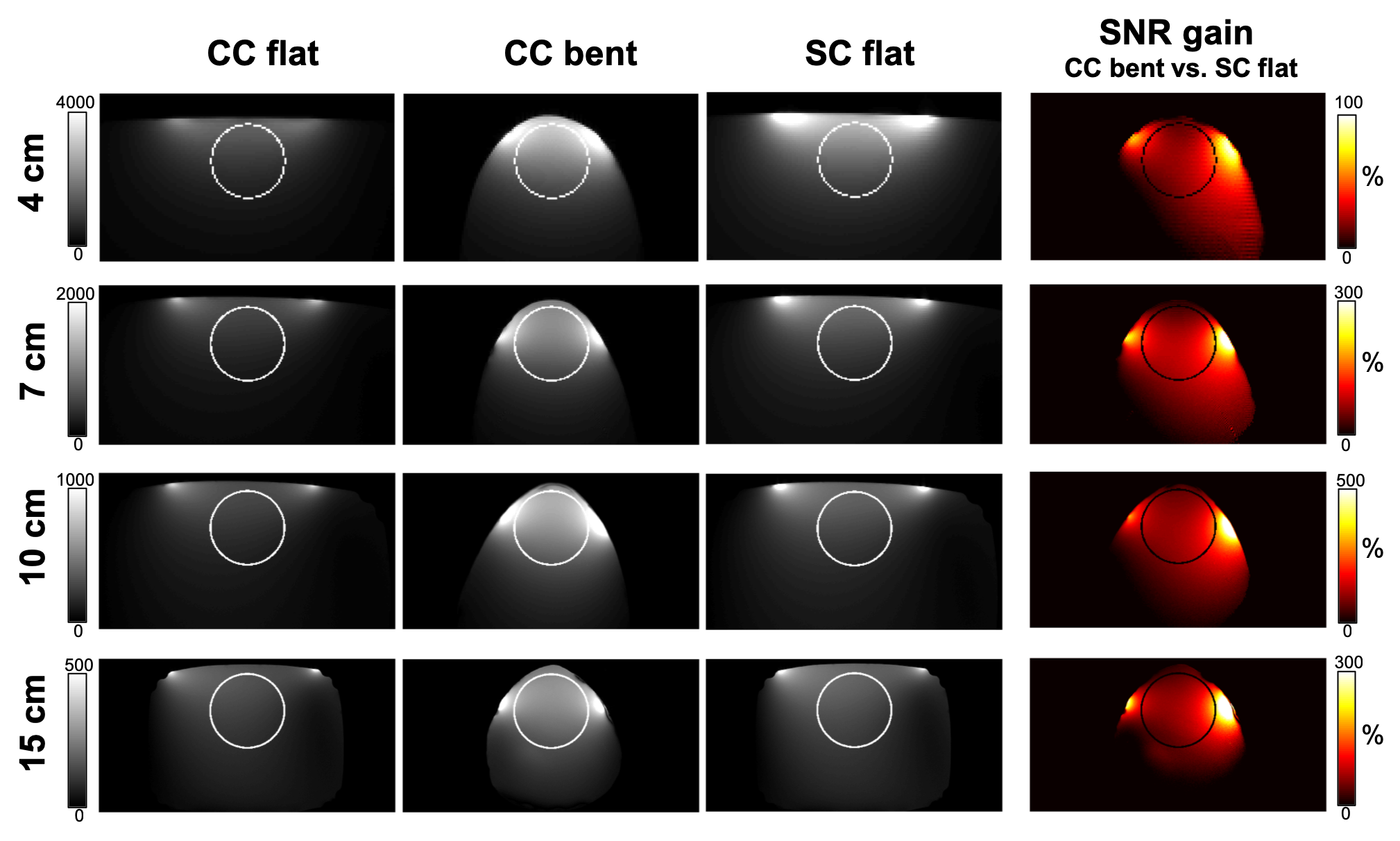
Initial B1+ mapping results with multi-gap CCs, using AD consisting of PIN-diodes shorting inner and outer conductor only at the coil port (Fig.2a), revealed non-sufficient decoupling of Rx and body coil, as presented in Fig.2b. It was found that CCs with more than one gap need a set of PIN diodes at every inner gap and chokes connecting the outer gaps (Fig.2c) to eliminate any residual resonances and therefore ensure satisfying AD as shown in Fig.2d. The examples shown in Fig.2b+d were measured with a 15 cm 2-turn 5-gap CC. For all CCs used in this study, the relative B1+ change without vs. with Rx coil present was max. 10-20 % over the whole phantom. Bench measurements summarized in Table 2 show the degradation of matching levels for strongly bent CCs, especially for the 7 and 10 cm CC. This can be explained by the frequency shift during bending - as the coils were initially tuned and matched in flat configuration on the 5l phantom - but can also be attributed to different phantom volumes used in bent configuration. For realistic use cases, coils would be tuned and matched to the average bending and a more specific load depending on the application. SNR maps calculated from GRE images and cropped to the respective coil size are presented in Fig.3. In a circular ROI, in flat coil position, less SNR for CCs can be observed than for SCs. Nevertheless, using the CC bent to the phantom results in an SNR gain averaged over the ROI of 24%, 80%, 116% and 69% for the 4, 7, 10 and 15 cm CC, respectively.Conclusion
We demonstrate the feasibility of MTMG-CC fabrication with commercially available coaxial cables and coil diameters ranging from 4 to 15 cm for different anatomical targets at 3 T. Together with SCs of same diameters, CCs were successfully employed as receive-only coils at 3 T MRI and demonstrate robustness regarding coil deformation as well as a significant SNR gain when form-fitted to the sample compared to the use of SCs in flat configuration. Possible applications range from hand, breast or larynx to abdomen MRI. In array configuration, ideal features could be combined, i.e. optimal penetration depth, large FOV coverage, high flexibility and wearability of lightweight CCs, improving patient comfort and image quality compared to rigid arrays with large variations in sample-coil distance.Acknowledgements
This project was funded by the Austrian/French FWF/ANR grant, Nr. I-3618, “BRACOIL“, and Austrian/French OeAD WTZ grant FR 03/2018.References
1. Kumar, A., Edelstein, W. A. & Bottomley, P. A. Noise figure limits for circular loop MR coils. Magn. Reson. Med. 61, 1201–1209 (2009).
2. Roemer, P. B., Edelstein, W. A., Hayes, C. E., Souza, S. P. & Mueller, O. M. The NMR Phased Array. Magn. Reson. Med. 16, 192–225 (1990).
3. Yang, X., Zheng, T., Wu, Y. & Finnerty, M. Coaxial cable magnetic resonance image (MRI) coils. (2017). US patent US9678180B2.
4. Zhang, B., Sodickson, D. K. & Cloos, M. A. A high-impedance detector-array glove for magnetic resonance imaging of the hand. Nat. Biomed. Eng. 2, 570–577 (2018).
5. Obermann, M. et al. Ultra-flexible and light-weight 3-channel coaxial transmission line resonator receive-only coil array for 3T. in Proc. Intl. Soc. Mag. Reson. Med. 27. 1558 (2019).
6. Stormont, R. S. et al. Systems for a radio frequency coil for MR imaging. (2019). US patent US20190277926A1.
7. Laistler, E. & Moser, E. Handy magnetic resonance coils. Nat. Biomed. Eng. 2, 557–558 (2018).
8. Nohava, L. et al. Flexible multi-turn multi-gap coaxial RF coils (MTMG-CCs): design concept and bench validation. in Proc. Intl. Soc. Mag. Reson. Med. 27. 565 (2019).
9. Czerny, R. et al. Flexible multi-turn multi-gap coaxial RF coils: enabling a large range of coil sizes. in Proc. Intl. Soc. Mag. Reson. Med. 27. 1550 (2019).
10. Darrasse, L. & Kassab, G. Quick measurement of NMR-coil sensitivity with a dual-loop probe. Rev. Sci. Instrum. 64, 1841–1844 (1993).
Figures