0749
Design of frequency division duplex RF system for frequency encoding using Bloch-Siegert shift1Department of Radiology and Biomedical Imaging, Yale School of Medicine, New Haven, CT, United States
Synopsis
In this work, we designed a frequency division duplex RF system for frequency encoding using Bloch-Siegert shift at very low field, with a modification of dual-band pass filters. Although the off-resonance frequency (870 kHz) is very close to the Larmor frequency (1 MHz), the applied off-resonance signal can be filtered out by a modified dual-band pass filter on the receive path. This system allows us to apply a 870 kHz transmit pulse while receiving 1 MHz signal from the RF coil.
Purpose
By applying off-resonant radiofrequency (RF) pulses, a spatially dependent frequency shift of the Larmor frequency is introduced1. Using this so-called Bloch-Siegert (BS) shift, it is possible to perform spatial frequency encoding without gradient coils2. However, simultaneous transmit (Tx) at the off resonance, and receive (Rx) at the resonance frequency is required for BS frequency encoding. One possible approach is using a frequency division duplex (FDD) RF system with RF filters. For our low field magnet3, it is challenging to design the RF filters since the two frequencies are close. In this work, we introduce a FDD RF system, which can be utilized to transmit a BS pulse during MR signal reception. The design goal of this system is to achieve a small insertion loss at 1 MHz and high insertion loss (> 58dB) at 870 kHz, between Tx and Rx ports.Methods
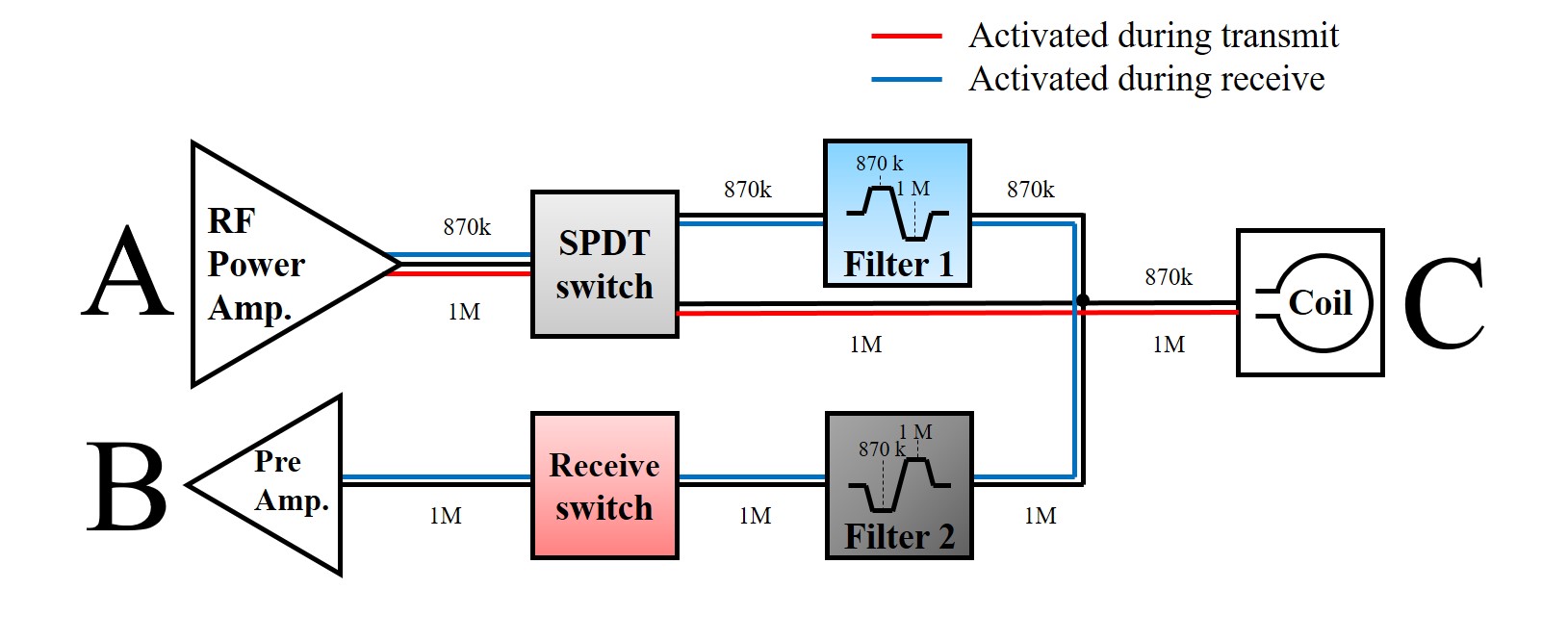
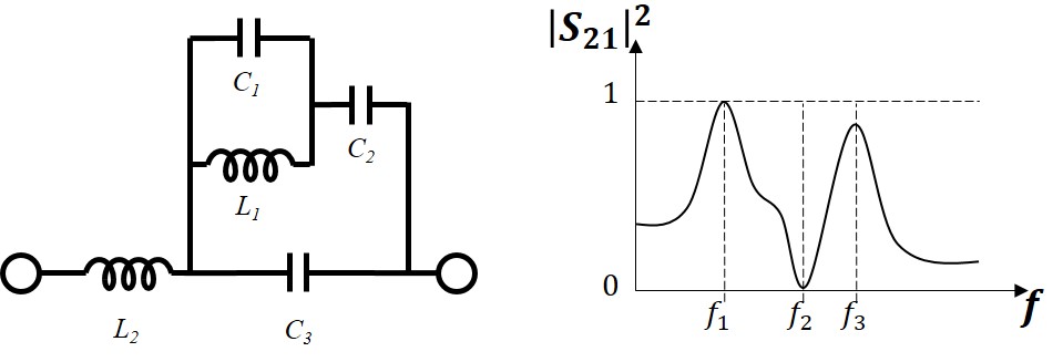
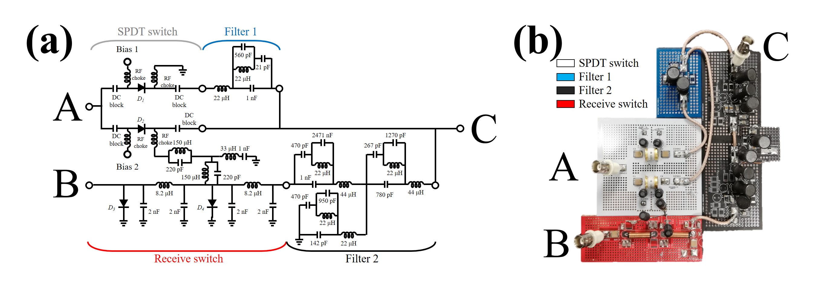
Fig. 1 shows the block diagram of the FDD RF system. A 1 MHz signal can be applied from the power amplifier (A) to the coil (C) during spin excitation (red line on Fig. 1), while this signal on receive pass (C to B) is blocked by receive switch. During signal reception, 870 kHz off-resonance signal for BS shift can be applied to the coil (A to C) while 1 MHz of the signal from the coil (C to B) is received by the preamplifier. Filter 1 and filter 2 are blocking the signal at 870 kHz and 1 MHz, respectively. A Dual-tuned coil can be used with this system. The maximum output power of the RF power amplifier (AR 0.5-15-1E3-3C, PCP, NY, USA) is 1 kW (60 dB) and the output P1dB and gain of the preamplifier (P4.2VD NMR, Ar2, CT, USA) are +22 dB and 20 dB, respectively. Thus, if the maximum power of the off-resonance signal is applied to the coil and the insertion loss of the filter 2 at 870 kHz is less than 58 dB, the signal can be saturated after amplification by preamplifier (60 dB - 58 dB + 20 dB = 22 dB). However, in practice, it is not simple to build the filter with greater than 58 dB insertion loss at 870 kHz while keeping small insertion loss at 1 MHz due to the frequencies being very close. In this work, dual-band pass filter4 was modified for this purpose (Fig. 2). For filter 1, f1 and f2 were tuned at 870 kHz and 1 MHz, respectively. A 3rd order dual-band pass filter, with two series filters and a shunt filter, was used for filter 2. The f2 and f3 of the series filters were tuned to 870 kHz and 1 MHz, respectively and the same configuration of filter1 was used as shunt filter of the filter 2. Figure 3 shows the schematic diagram and the photo of the whole RF system. It is designed that the diodes D2, D3, and D4 are tuned on/off simultaneously. During the spin excitation, 200 mA of the forward current can be applied to the D2 and split into D3 and D4. However, RF signal applied from port A can be transmitted to port B through the DC bias line. For this reason, a 3rd order band stop filter was added between D2 and D3. The S-parameters between the ports A, B, and C were measured for Tx and Rx conditions using vector network analyzer.Results
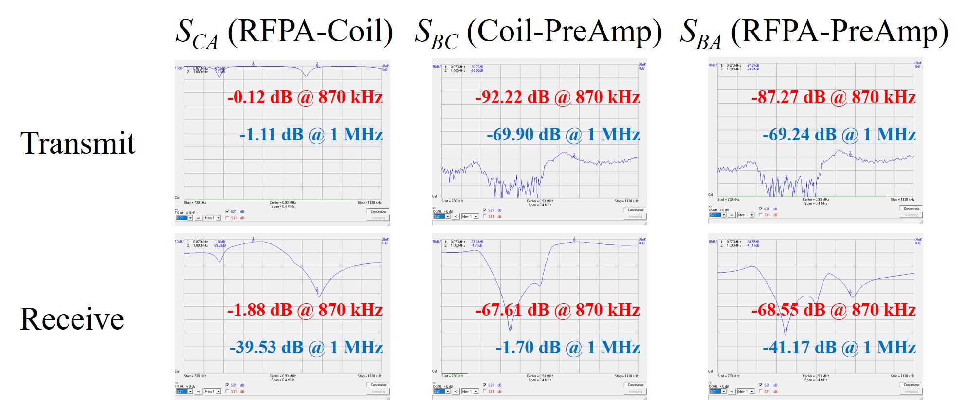
For the spin excitation, the port A and the port C are connected by turning on the D2, while the impedance between the port B and the port C is high by the receive switch with turning on D3 and D4. As shown in Fig. 4, the insertion loss between port A and C was 1.11 dB at 1 MHz, and 69.24 dB between port A and B. Thus, an RF pulse with a frequency of 1MHz can be applied from port A to port C, without it reaching port B. The insertion loss between port A and C was 1.88 dB at 870 kHz and 66.55 dB between port A and B. When D1 is turned on, off-resonance signal can be applied from port A to port C but is blocked by filter 2. At the same moment, receive signal from port C with 1 MHz frequency can be transmitted to port B but is blocked by filter 1. The insertion loss between port B and C was 67.61 dB and 1.70 dB at 870 kHz and 1 MHz, respectively and it between port A and C was 39.53 dB during the signal reception.Discussion / Conclusions
We have built and demonstrated the performance of an FDD system for frequency encoding using Bloch-Siegert shift. The insertion loss from Tx port to Rx port at 870 kHz was about 69 dB which is sufficient for amplification of the Rx signal without saturating the preamplifier. If necessary, the isolation can even be improved further by increasing filter 2 to a higher order filter. Insertion losses for other signal paths (1 MHz Tx, 870 kHz Tx, and 1 MHz Rx) were less than 2 dB which is sufficient for RF signal transport.Acknowledgements
No acknowledgement found.References
1. F. Bloch and A. Siegert, “Magnetic resonance for nonrotating fields,” Phys. Rev., vol. 57, no. 6, pp 522-527, Mar. 1940.
2. Z. Cao, E. Y. Chekmeney, and W. A. Grissom, “Frequency encoding by Bloch-Siegert shift,” in Proc. 22nd Annu. Meet. Int. Soc. Magn. Res. Med., Milano, Italy, May 10-16, 2014.
3. R. T. Constable, C. Rogers III, B. Wu, K. Selvaganesan, and G. Galiana, "Design of a novel class of open MRI devices with nonuniform B0, field cycling, and RF spatial encoding," in Proc. 27th Annu. Meet. Int. Soc. Magn. Res. Med., Montreal, Canada, May 10-13, 2019.
4. H. Joshi, and J. Chappell, “Dual-band lumped-element bandpass filter,” IEEE Trans. Microw. Theory Tech., vol. 54, no. 12, pp. 4169-4177, Dec. 2006.
Figures