0748
Asymmetric Dipole Head Array for Ultra-High-Field Magnetic Resonance Imaging Turns “Dielectric Resonance” from an Enemy to a Friend.
Nikolai Avdievich1, Georgiy Solomakha2, Loreen Ruhm1, Jonas Bause1,3, Anke Henning1,4, and Klaus Scheffler1,5
1Max Planck Institute for Bilogical Cybernetics, Tuebingen, Germany, 2Nanophotonics and Metamaterials, ITMO University, St.Petersburg, Russian Federation, 3Graduate School of Neural and Behavioral Sciences, Tuebingen, Germany, 4Advanced Imaging Research Center, University of Texas Southwestern Medical Center, Dallas, TX, United States, 5Department for Biomedical Magnetic Resonance, University of Tübingen, Tuebingen, Germany
1Max Planck Institute for Bilogical Cybernetics, Tuebingen, Germany, 2Nanophotonics and Metamaterials, ITMO University, St.Petersburg, Russian Federation, 3Graduate School of Neural and Behavioral Sciences, Tuebingen, Germany, 4Advanced Imaging Research Center, University of Texas Southwestern Medical Center, Dallas, TX, United States, 5Department for Biomedical Magnetic Resonance, University of Tübingen, Tuebingen, Germany
Synopsis
We developed a novel 9.4T (400MHz) human head transceiver array consisted of 8 optimized bent folded dipole antennas. Due to an asymmetrical shape of dipoles (bending) and the RF shield, the array simultaneously excites two modes including a circular polarized mode of the array itself, and the TE mode of the human head. Mode mixing can be easily controlled by changing the folded length. As a result, the new array provides superior whole-brain coverage compared to various 8-element loop and dipole arrays or even to a more complicated 16-element loop array. In addition, the maximum local SAR is substantially reduced.
Purpose:
To improve the transmit (Tx) performance and brain coverage of a human head array coil at 9.4 T (400 MHz), a novel dipole antenna array design was developed, constructed, and evaluated.Introduction:
Clinical application of ultra-high field (UHF, >7 T) MRI, is still hindered due to technical hurdles associated with imaging of large (comparable to the RF wave length) human objects (body, head). Resulting issues include a significant increase of the maximum local SAR, and a strong inhomogeneity of the Tx RF magnetic field, B1+ characterized by a pattern with strongly decreased peripheral values (~2 times for a head (1) at UHF). Both effects are associated with a so-called “dielectric resonance” or standing wave. Importantly, this effect is seen along all three directions and considerably limits whole-brain coverage at UHF. Improvement of the B1+ homogeneity and coverage can be achieved by using multi-loop Tx-arrays, e.g. single-row 8-element (1x8) arrays (2,3), or double-row 16-element (2x8) arrays (2,4-6). However, an adequate whole-brain coverage was demonstrated only by using multi-row arrays (e.g.2x8) capable of 3D RF shimming (7). In this work, we developed a novel human head 9.4 T transceiver (TxRx) 1x8 array consisting of bent folded dipole antennas, which substantially simplifies the Tx-coil design but provides a whole-brain coverage that is better than that of a more complex 2x8 loop array.Methods:
Using electromagnetic (EM) simulations we demonstrate that in the presence of the RF shield, the bent dipole array not only produces its own circularly polarized (CP) mode but also couples to the intrinsic transverse electric (TE) mode (“dielectric resonance”) of the sample (Fig.1), i.e. a phantom or a human head. The TE mode resonates near 400 MHz and is characteristic of tangential electric field, Et, near the center of the sample (Fig.1). We show that the mode mixing, firstly, improves the longitudinal coverage of the Tx-array. Secondly, it helps to reduce the maximum local SAR. This, however, can also decrease the array Tx-performance since the TE mode also possesses Hz component of the magnetic field. Thus, mode mixing has to be optimized by adapting the dipole geometry. EM simulations of the local SAR and B1+ were performed using CST Studio Suite 2017 (CST, Darmstadt, Germany) and the time-domain solver based on the finite-integration technique. Two models were used, i.e. an elliptical phantom (ε=58.6, σ=0.64 S/m), and the virtual family model “Duke”. After numerical optimization, we constructed and tested the dipole TxRx-array consisting of eight 30-mm bent folded dipoles (30 mm – the folded portion length). Array measured 200 mm x 230 mm in clearance, and 175 mm in length. We compared the performance of the new array to that of 1x8 (3) and 2x8 (6) surface loop TxRx-arrays with the same clearance. While the 2x8 array had the same length, the 1x8 array was shorter (100 mm). All arrays were shielded (distance to the RF shield - 40 mm). All data were acquired on a Siemens Magnetom 9.4 T human imaging system. Experimental B1+ maps were obtained as previously described (8).Results and Discussion:
Fig.2 shows the effect of mode mixing on the cylindrical phantom in the presence of an RF shield. While straight dipoles (Fig.2C) reveal only a minor quantitative difference for shielded and unshielded arrays, bent dipoles (Fig.2D) demonstrate a large qualitative and quantitative difference in both B1+ and SAR distributions. Firstly, shielded bent dipoles extend the B1+ map longitudinally. Secondly, appearance of the non-zero SAR at the center of the phantom indicates coupling to the TE mode. Fig.3 shows the effect of bending and folding dipoles on the Duke voxel model. Clearly, mixing of modes growths with increasing the folded portion length, which is indicated by the stronger Hz component (Fig.3B) and SAR increase near the brain center (Fig.3C). Mode mixing also improves the brain coverage (Fig.3D). Thus, changing the folded portion length provides an easy way of optimizing the Tx-performance. Table 1 summarizes results of numerical optimization. The 30-mm bent folded dipoles provide the best <B1+>/√SAR value. Finally, Fig.4 shows an experimental comparison of the new dipole array performance to that of the 1x8, and 2x8 surface loop arrays. As seen from the figure, the dipole array provides better coverage than both loop arrays.Conclusion:
We developed a novel 9.4T human head TxRx-array consisted of 8 optimized 30-mm bent folded dipole antennas. Due to the asymmetrical shape of dipoles (bending), the array couples to the TE mode of the human head. Adjustment of the folded length provides for a simple way of reducing the maximum local SAR and improving the longitudinal coverage.Acknowledgements
SG acknowledges a support by Government of Russian Federation (Grant 08-08) and Ministry of Education and Science of the Russian Federation (No. 3.2465.2017/4.6). Funding by the European Union (ERC Starting Grant, SYNAPLAST MR, Grant Number: 679927) is gratefully acknowledged by AN and RL.References
1) Vaughan JT, Garwood M, Collins CM et al. Magn Reson Med 2001;46:24-30. 2) Avdievich NI, Giapitzakis IA, Pfrommer A et al. Magn Reson Med 2018;79(2):1200–1211. 3) Avdievich NI. Appl Magn Reson 2011;41(2):483-506. 3) Adriany G, Van de Moortele P-F, Ritter J et al. Magn Reson Med 2008;59:590-597. 4) Gilbert KM, Belliveau J-G, Curtis AT et al. Magn Reson Med 2012;67:1487–1496. 5) Shajan G, Kozlov M, Hoffmann J et al. Magn Reson Med 2014;71:870–879. 6) Avdievich NI, Giapitzakis IA, Pfrommer A et al. NMR in BioMed 2018; 31(9):1-13. 7) Hoffmann J, Shajan G, Scheffler K et al. Magn Reson Mater Phy 2014;27(5):373-386. 8) Yarnykh VL. Magn Reson Med 2007;57:192-200.Figures
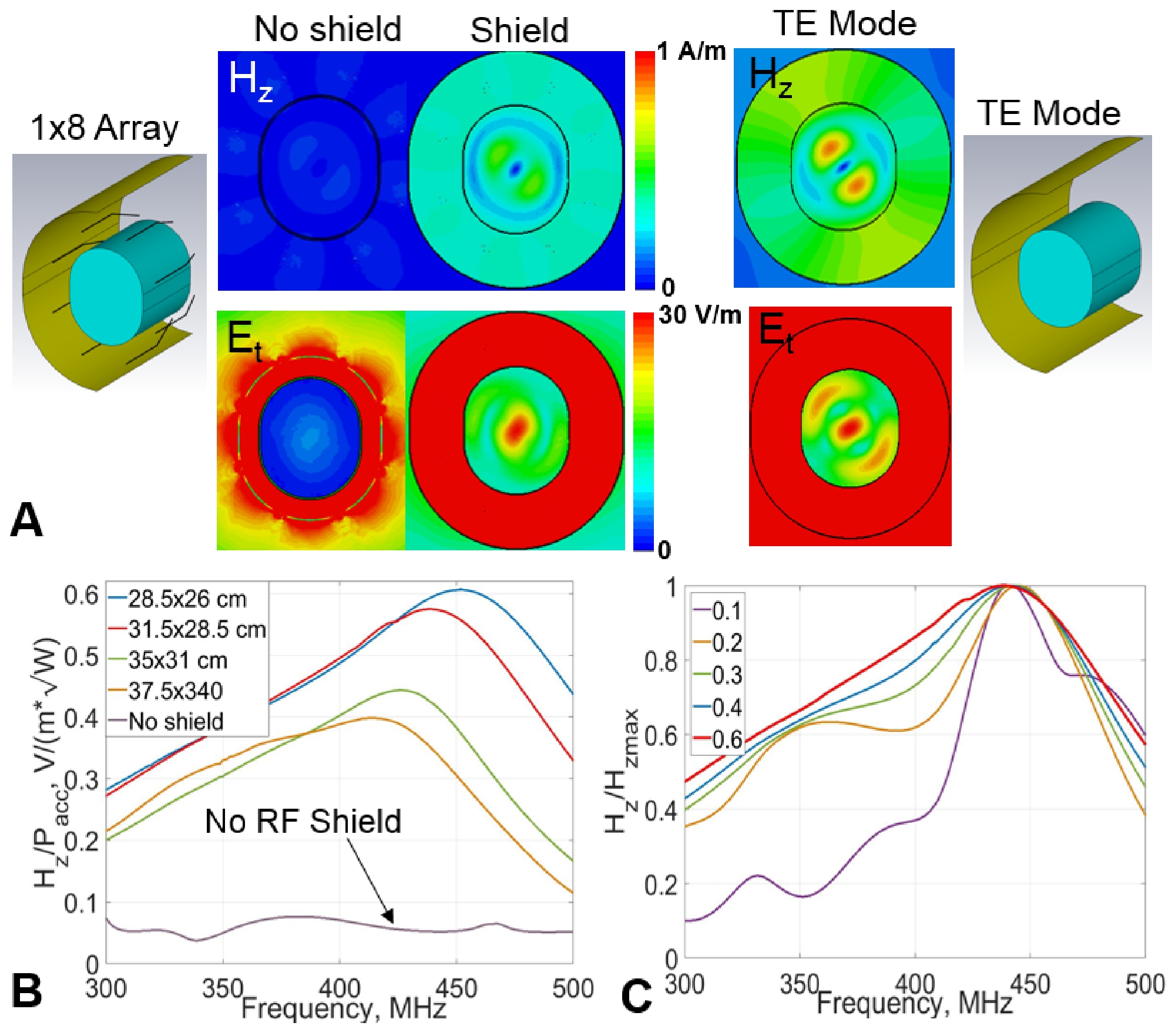
Figure 1. Simulated central transversal map of the Hz (parallel to the cylinder axis) and Et (tangential) components
of the RF field, generated inside the elliptical phantom by the 8-element 30-mm
bent folded dipole array with and without the RF shield. Frequency dependencies (“resonance curves”) of the RF
field of the phantom TE mode simulated for different sizes of the RF shield (B)
and conductivity (C) values using Hz
component. In
Fig.1B curves are normalized to the 1 W of incident RF power. In Fig.1C curves are normalized to maximum amplitudes.
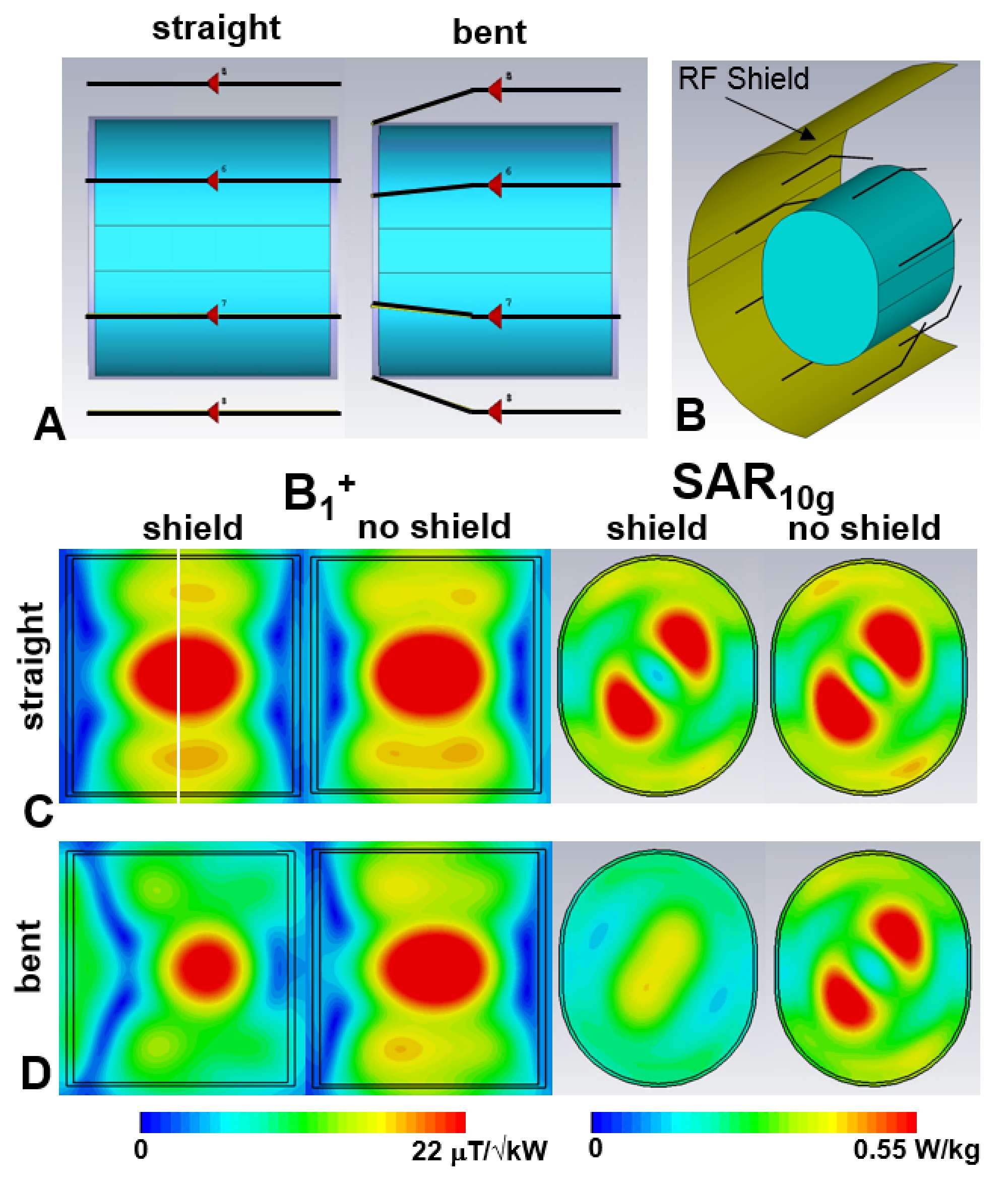
Figure 2. Simulation models of straight and bent 8-element
dipole arrays loaded by the elliptical phantom. The RF shield is hidden for
better visualization. B) Simulation model of the 1x8 bent dipole array
showing the RF shield. Simulated central sagittal B1+
and transversal SAR10g maps obtained
using straight (C) and bent (D) 8-element dipole arrays
with and without the RF shield. Transversal
SAR10g maps are shown for the location marked by a white line in
Fig.2C. Elliptical phantom measures 140 mm in width, 180 mm in height, and 200 mm in length.
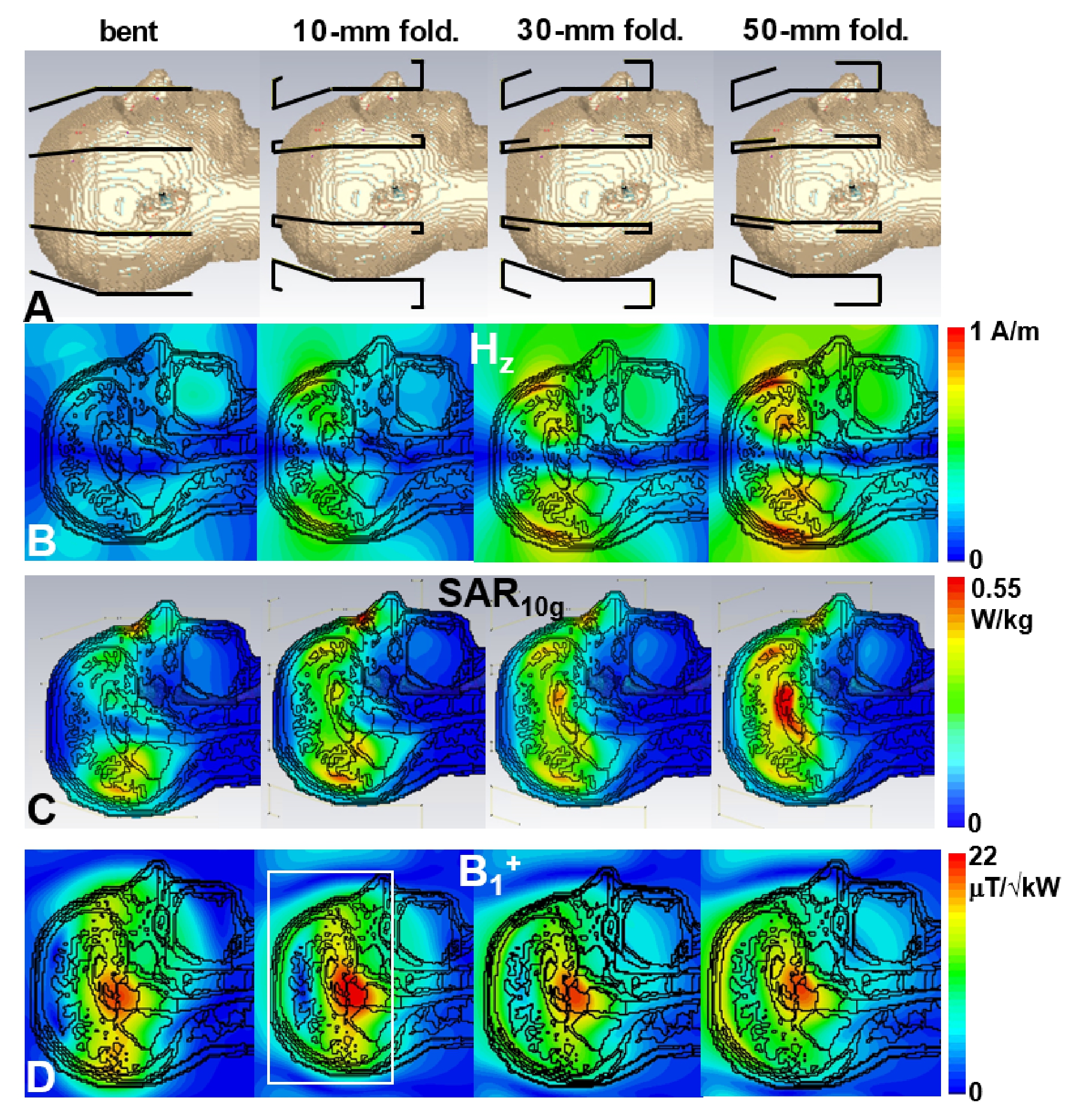
Figure 3. A) Simulated models of different
8-element dipole arrays loaded by the Duke voxel model. All ports and the RF
shield are hidden for better visualization. B) Simulated
central sagittal Hz maps
obtained using arrays shown in Fig.3A. C) Simulated
central sagittal SAR10g maps obtained using arrays shown in Fig.3A.
D) Simulated central sagittal B1+ maps obtained using arrays shown in
Fig.3A. Fig.3D shows the 130-mm transversal slab used for B1+ averaging.
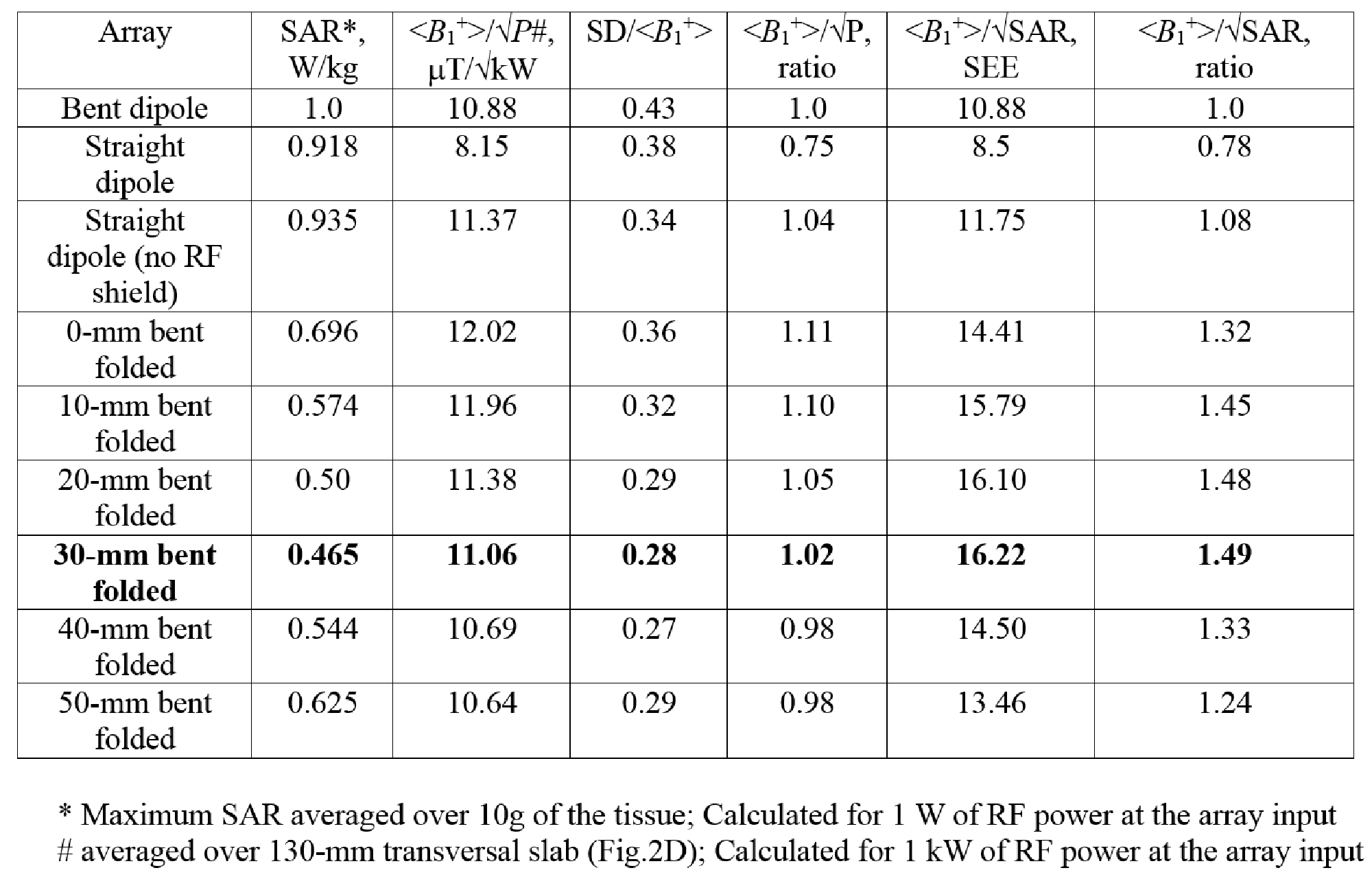
Table 1. Numerical Comparison of Tx-performance
of different 1x8 dipole arrays.
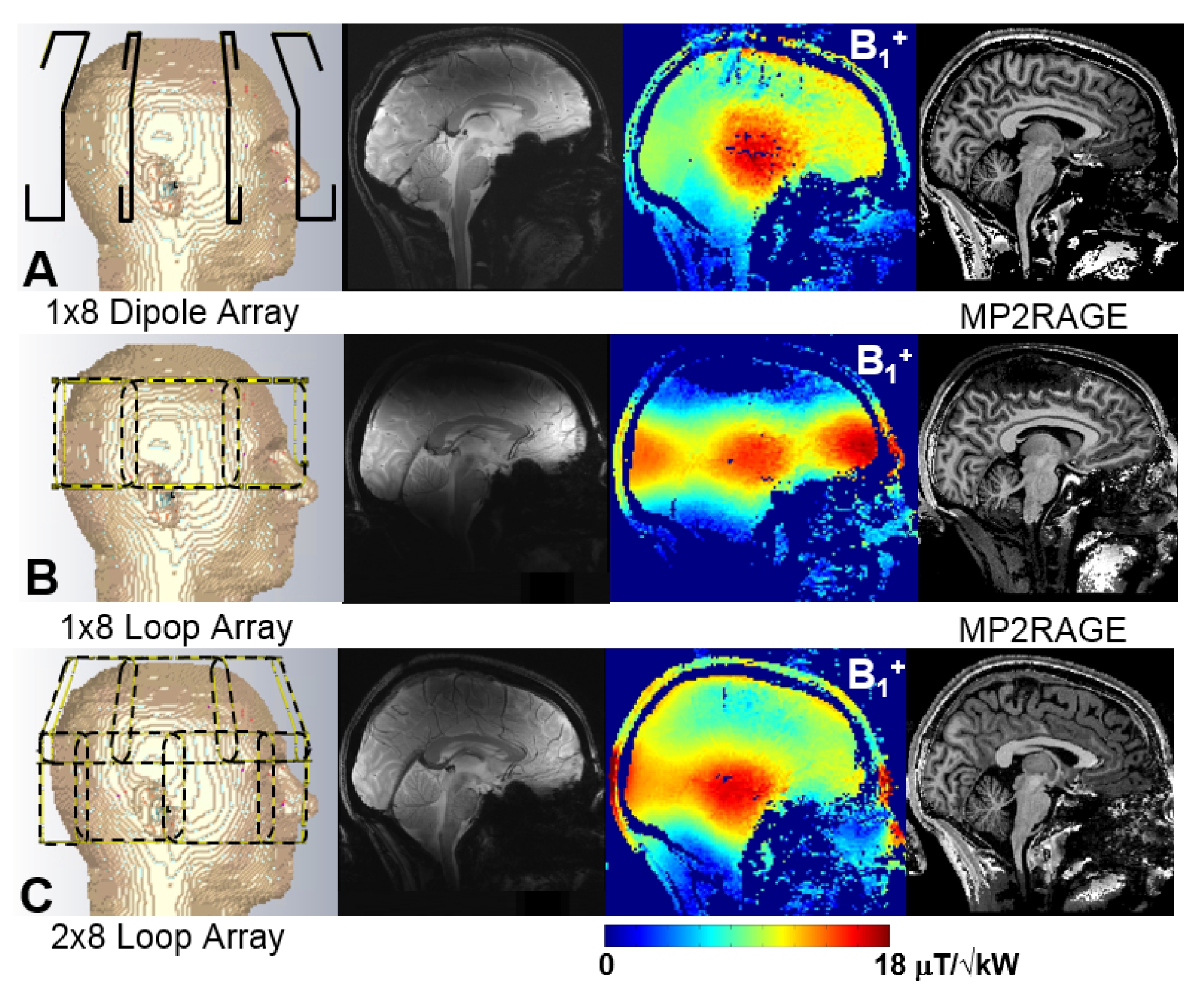
Figure 4. Comparison of experimentally
measured data obtained using the new 1x8 30-mm bent folded dipole TxRx-array
(A), 1x8 surface loop TxRx-array (B), and 2x8 surface loop TxRx-array (C)
including GE images, B1+
maps, and 1-mm isotropic MP2RAGE images. All images and maps are shown for the
central sagittal slices. CST models of arrays loaded by the Duke voxel model
are shown on the left.