0747
Customized B1+-Shaping using Multi-Channel Transceiver Array Prototype for 7T Cardiac MRI with Central Elements Symmetry1Chair of Cellular and Molecular Imaging, Comprehensive Heart Failure Center (CHFC), University Hospital Würzburg, Wuerzburg, Germany, 2RAPID Biomedical, Rimpar, Germany, 3Department of Internal Medicine l, University Hospital Wuerzburg, Wuerzburg, Germany, 4Institute of Diagnostic and Interventional Radiology, University Hospital Wuerzburg, Wuerzburg, Germany
Synopsis
Multiple element transmits and receive (mTx) phased arrays allow for improvement of the image quality in ultra-high-field (B0≥7T) cardiac MRI (cMRI). The optimization performed for both transmit and receive requires novel approaches regarding mTx element geometry and positioning making а B1-shimming of such arrays a complicated problem. We have demonstrated the initial experience of the case-specific B1-shimming of the mTX-array design for cMRI at 7T. The design with a central symmetry of elements and tailored cost function used for driving phases optimization allows for high flexibility in shaping of predefined target B1+ profiles.
Introduction
Multiple transmit (mTx) phased arrays are a key technology for ultra-high-field (UHF) MRI1-3. Manipulation of complex amplitudes for the individual array elements allows for achieving the desired spatial distribution of the B1+-field within the imaged field-of-view. The full parallel transmit (pTX) mode operation of cardiac arrays at 7T array is still a challenge due to demanding SAR calculation. Therefore, most of the UHF cardiac studies are still done using single TX mode requiring preliminary static B1-shimming of the mTX arrays. Here, we aim to demonstrate initial experience of the customized phase-based B1-shimming of mTX array developed for the cardiac MRI at 7T in humans.Theory
For the equal driving amplitudes in each element the combined B1+-field of an mTX-array is described as$$B_{1,c}^+=\sum_{k=1}^N{b_{1,k}^+(\phi_k)} (1)$$
where b1,k+ is profile of corresponding Tx-element. B1+-shimming is performed by control of the phase vector {Φ}={Φ1..ΦN} to achieve the targeted properties of B1c+. Phase vectors providing targeted shaping of B1c+ can be found by maximizing an optimization cost function (OCF). We used OCF combining three terms F1, F2 and Txeff which are targeted to: (i) maximize the homogeneity of B1c+, (ii) minimize the destructive interferences in the targeted FOV and (iii) maximizing the transmission efficiency of the array respectively. The impacts the factors (i) and (ii) are balanced via weighting coefficient.
$$Tx_{eff}=\frac{|\sum_k^Nb_{1,k}^+(\phi_k)|}{\sum_k^N|b_{1,k}^+|};
F_{1}=\frac{[mean(B_1^+)]^2}{std(B_1^+)(max(B_1^+)-mean(B_1^+))}; F_{2}=\frac{min(B_1^+)\cdot [mean(B_1^+)]^2}{std(B_1^+)} (2)$$
$$F_{opt}=(w\cdot F_1+\sqrt{(1-w^2)}F_2)\cdot Tx_{eff} (3)$$
Materials and Methods
The mTx array consists of an anterior and a posterior part allocating 8 elements each with the possibility of control of the driving phases by connecting BNC cables (Figure 1a). In single TX mode all channels are driven with equal magnitudes via power combiner. In pTX mode elements are pairwise connected to the 8 TX-channels RFPA. B1+-profiles of individual channels were simulated using CST software (CST, Darmstadt, Germany). The computation of combined B1+ maps and optimization of phase vectors was done using in-house developed Matlab (2017) toolbox4. A plexiglass phantom filled with PVP solution (e»55) was used for the validation of the simulation by MRI-measurements. The B1+-profiles for human studies was simulated using Duke and Ella human voxel models (ViP2.0 IT’IS Foundation, Switzerland). All MRI measurements were done using a 7T Magnetom(TM) Terra scanner (Siemens, Erlangen, Germany ). Volunteer measurements were performed with the permission of the local Ethics Committee (#7/17-sc). Cardiac scans included GRE CINE with short and long-axis views of the heart, B1+-maps, g-factor maps and T2*-maps performed with mGRE. For comparison, the same scans were done using the scanner vendor-supplied 1Tx/16Rx cardiac array with fixed phases and rectilinear elements arrangement. Two phase vectors {Φ}D,homo,{Φ}E,homo were computed using with the maximizing homogeneity of for Duke and Ella model respectively using w=0.98 . The vector {Φ}D,maxmin was targeted on maximizing minimums of in the anterior region and computed Duke model (w=0.2).Results
Figure 1b demonstrates examples of the validation of the simulated B1c+ using the human thorax phantom. The result of the phase optimization in the marked region is shown for comprehensibility. Figure 2a demonstrates the position of the array on the human thorax. Figure 2b shows the examples of the optimizations of with “homogeneity” and “max-minimum” phasing vectors. Figure 3 demonstrates the comparison of the tested prototype B1-shimming with the “homogeneity vector" and standard cardiac array with fixed phasing. The dedicated customized phasing allows avoiding the “overshoot” of the in the anterior region (Fig 3a) which leads to artifacts in the short-axis view CINE images acquired using the array with fixed phases on the same volunteer (Figure 3b). Figure (3c) shows the R=3 g-factor map of both arrays in the short-axis plane. Figure 4 shows CINE images of female (60kg) volunteer using the prototype array with setting all 3 tested phase vectors. Figure 4(b) shows the profiles along marked lines characterizing blood-to-tissue contrast in each case. Figure 5 demonstrates the usage of {Φ}D,maxmin vector to acquire high-resolution T2*-maps on а male volunteer (75kg). Figure 5a (right) shows variation in mGRE images depending on the TE-time. Plots 5b demonstrates the goodness of fit of signal-time curves at selected positions. Figure 5c shows the T2*-maps reconstructed on pixel basis for the diastolic and systolic phases.Discussion
Customized B1+-shaping worked very flexibly when used with the central array's element's arrangement. Using phase manipulation with 16 elements, the array prototype allows for the flexible shaping of the B1+-profile with predefined properties in terms of homogeneity or maximizing flip-angle. In particular, the phase vector adjusted for the specific human model shows an essential advantage over others (Figure 4) in terms of anatomic visualization providing both homogeneity and blood-to-tissue contrast. Nevertheless, for specific applications (e.g T2*-mapping) the OCF could be adjusted for maximizing acquired signal and partially sacrificing of homogeneity of the signal across FOV due to normalization performed on pixel basis for the T2* computing.Conclusion
The initial testing uncovered the high potential of both novel multi-elements transmits arrays design and the optimization methodology for application in cardiac MRI of at 7T. The implemented geometry with central symmetry of elements arrangement allows for high flexibility in shaping predefined B1+-profiles and improved g-factor for cardiac imaging in comparison to a traditional rectilinear element positioning.Acknowledgements
Financial support: German Ministry of Education and Research (BMBF, grants: 01EO1004, 01E1O1504).References
[1] Graessl, et al., (2014), Modular 32-channel transceiver coil array for cardiac MRI at 7.0 T, MRM, 72(1), 276-290.
[2] Thalhammer, et al., (2012), Two-dimensional sixteen channel transmit/receive coil array for cardiac MRI at 7.0 T: design, evaluation, and application. JMRI, 36(4), 847-857.
[3] Oezerdem, et al., (2016), 16-channel bow-tie antenna transceiver array for cardiac MR at 7.0 tesla, MRM, 75(6), 2553-2565.
[4] M. Terekhov, I. Elabyad, M. R. Stefanescu, L. M. Schreiber. Optimization of Phase Presets of Multi-Channel Transceiver Arrays for 7T Large Animal Cardiac MRI, ISMRM 2019, Montreal, Canada
Figures
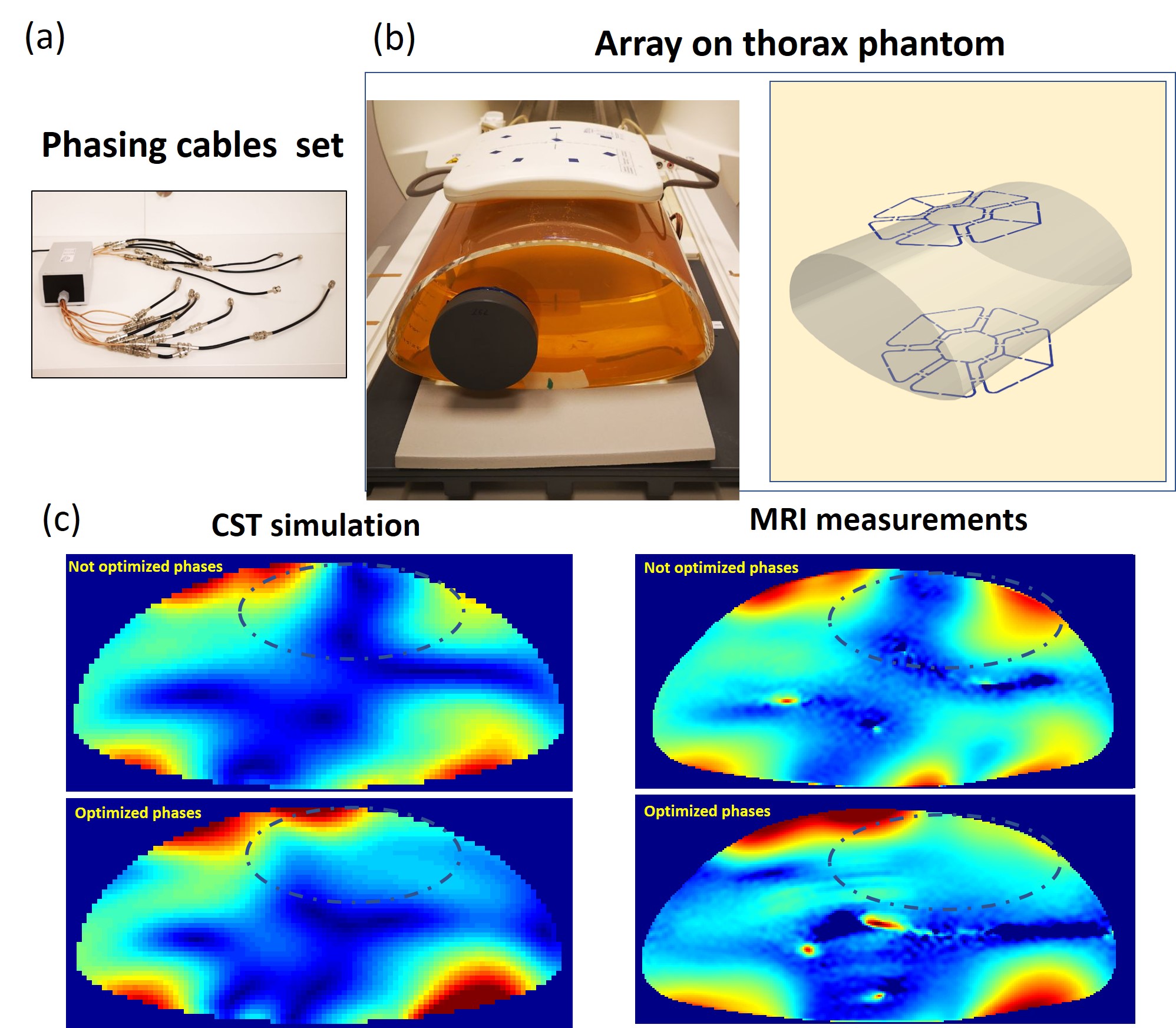
Figure 1
(a) .Array prototype with central symmetrical elements arrangement (top) Power splitter with phasing cables (bottom); (b) Thorax phantom with PVP filling and array position on the CST model. 40 million mesh cells were used with a total computation time of ~48 hours using 2 Tesla K80 GPU; (c)MRI measurements validation of the optimized phase setting computed using phantom’s CST model. The OCF [3] with w=0.4 was used for finding the optimized phase vector removing the destructive interference in the targeted region ( dash line)
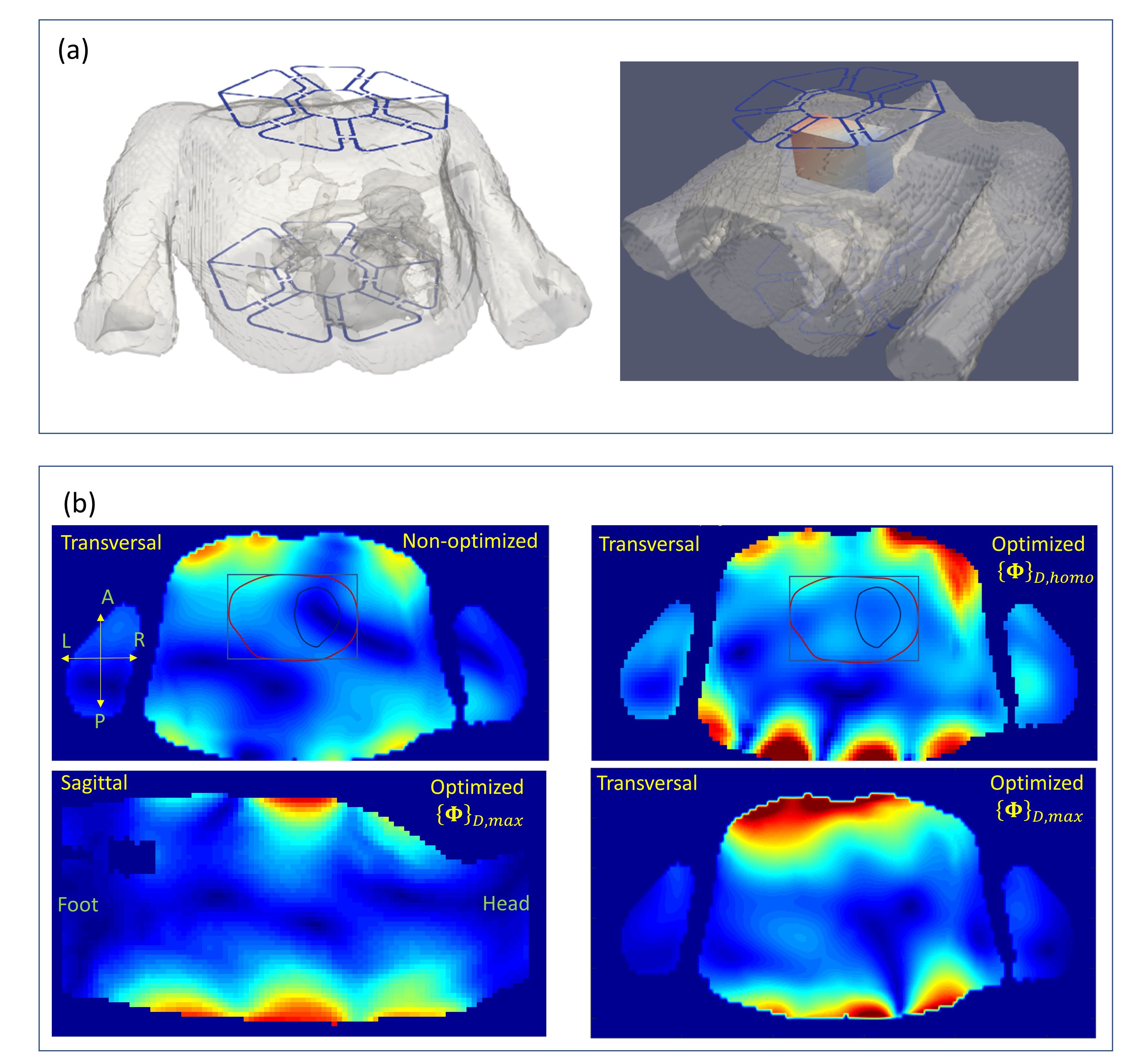
Figure 2
(a) Position of the array on the human model used for the simulation of the arrays B1+ profile and approximate position of the optimized ROI within thorax.
(b) Examples of the optimized combined B1+ profiles computed for different weighting coefficient in cost function [3]. Transversal and sagittal slices at the geometrical center of the array are shown. For the vector optimization targeted to maximize the flip-angle in the anterior part of the thorax the targeted ROI was extended on 25 mm in left and right direction and shifted on 20mm to the anterior direction.
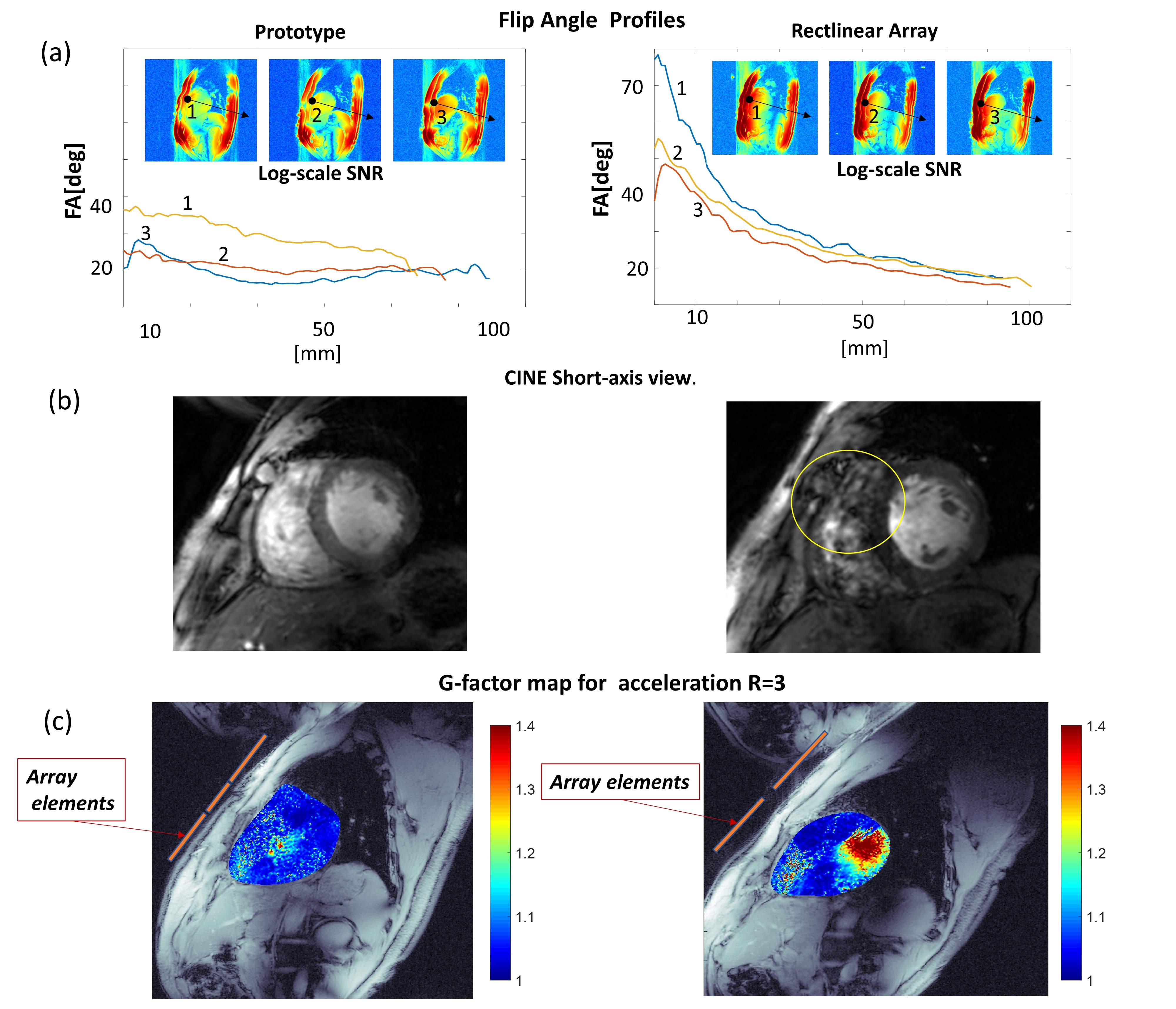
Figure 3
(a) Flip angle maps of the prototype with “homogeneity” phase vector measured on the male volunteer (75kg). On the left panel, the same plots are shown for the commercial array with a rectilinear design. The significantly larger gradient of the FA in AP direction is observed in the latter case. This is manifested in artifacts (yellow line) in the anterior part on the CINE images (Figure (b)).
Figure (c) shows the g-factors maps of both arrays at R=3. The essential increase of g-factor is observed for rectilinear array in comparison to the novel prototype at this slice orientation.
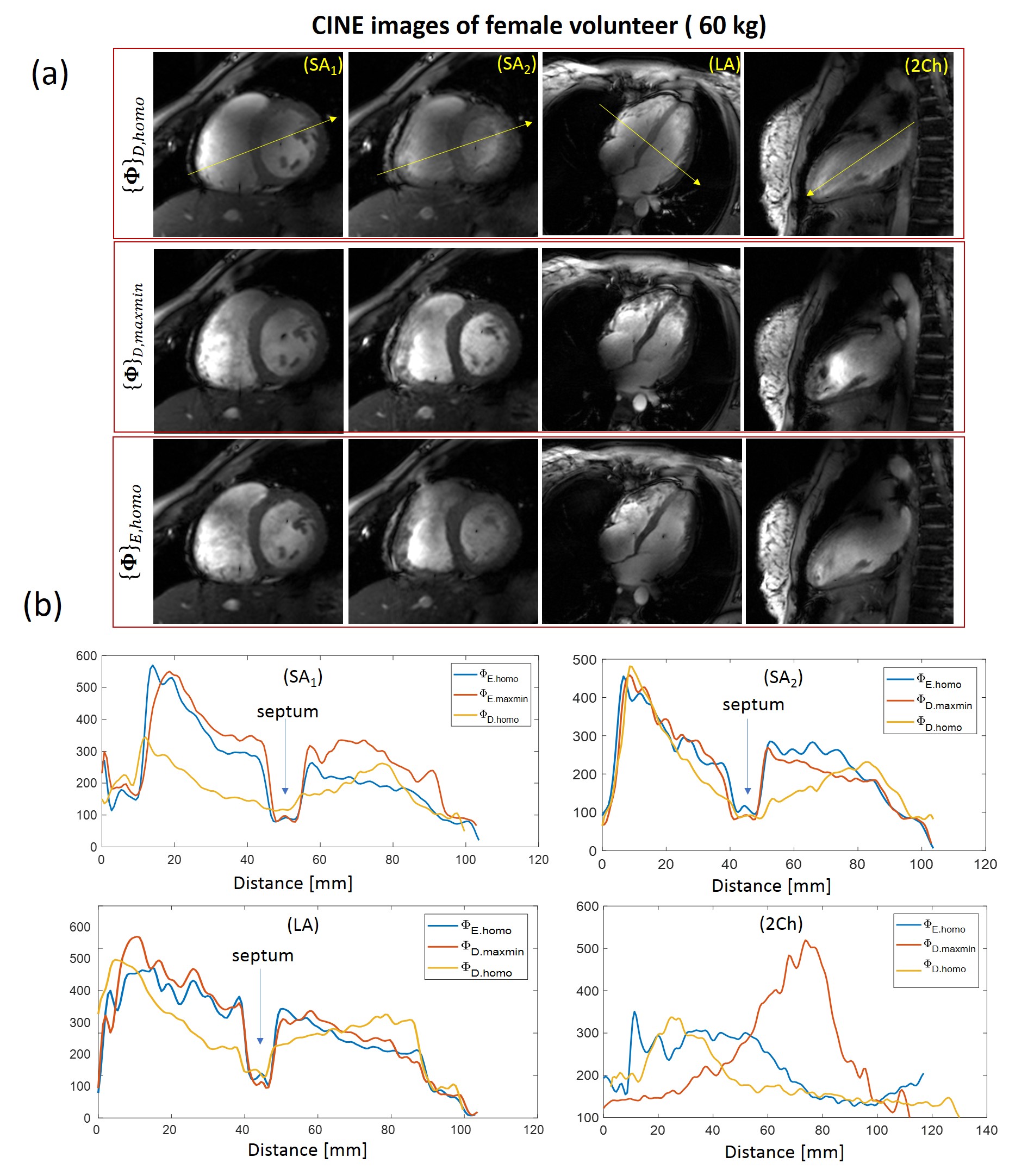
Figure 4
CINE images of female volunteer (60kg) acquired with 3 tested phasing vectors (a). Short-axis long-axis and two-chamber views are shown. For the female volunteer the optimal image quality was for the vector optimized using Ella model. It provides optimal blood-to-tissue contrast as shown on Figure (b). The vector optimized for the homogeniety with Duke model shows much less contrast at septum. The optimization with vector {Φ}D,maxmin provides sufficiently good quality in SA and LA views yet suffers from overshot of FA in two-chamber view at the anterior location.
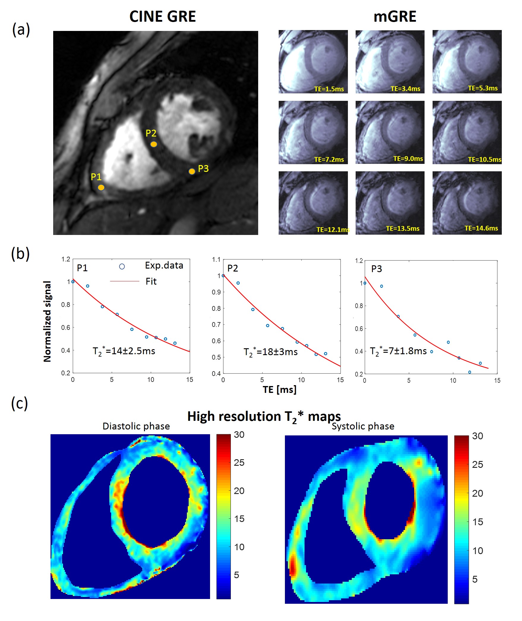
Figure 5
{Φ}D,maxmin vector used for the high resolution (0.6mm/pixel in-plane) T2* mapping on male volunteer (75kg). Fig. 5a (right panels) shows changes of the signal with TE-time (marked on images). Plots 5b demonstrates the goodness of fit of signal-time curves at selected positions. Due to normalization of the signal on pixel basis for fitting the increased gradient of the flip-angle in AP direction plays no role. Figure 5c shows the T2*-maps reconstructed on pixel basis for the diastolic and systolic phases