0746
Effect of Coaxial Feed Cables on the Performance of Loop & Dipole Arrays at Ultra High Frequencies1Center for Magnetic Resonance Research, Minneapolis, MN, United States
Synopsis
We designed and built three elliptically arranged 8- and 16-channel transceiver dipole and loop arrays for the human head applications and evaluated the influence of coaxial feed cables on the overall array performance. The influence of coaxial feed cables was evaluated in simulation and compared against actual built arrays in terms of B1+ and SAR efficiency. For all three arrays we consistently observed ~30 % performance reduction compared to the “ideal” coil with no coaxial cables.
Introduction
At ultra-high fields, multi-element transmit arrays with independent channels are essential to achieve acceptable B1+ field homogeneity and to optimize transmit efficiency [1-3]. As a transmitter, dipole head arrays are desirable for fields above 7T and it is predicted that they can yield optimal coil performance for central locations [4-6]. However for realistic head array housings the coaxial feed cables have to be routed in close proximity to one leg of the dipole. To investigate the influence of this required non-ideal coaxial feed path we built a 16-channel dipole head array and compared it with an 8-channel loop and an 8-channel dipole array. For each coil array we compared a realistic coaxial feed routing path to a more ideal – but in practice unrealistic- cable path. We furthermore evaluated this effect in simulations which could be performed with and without coaxial cables thus allowing comparison to an ‘ideal’ coil.Methods
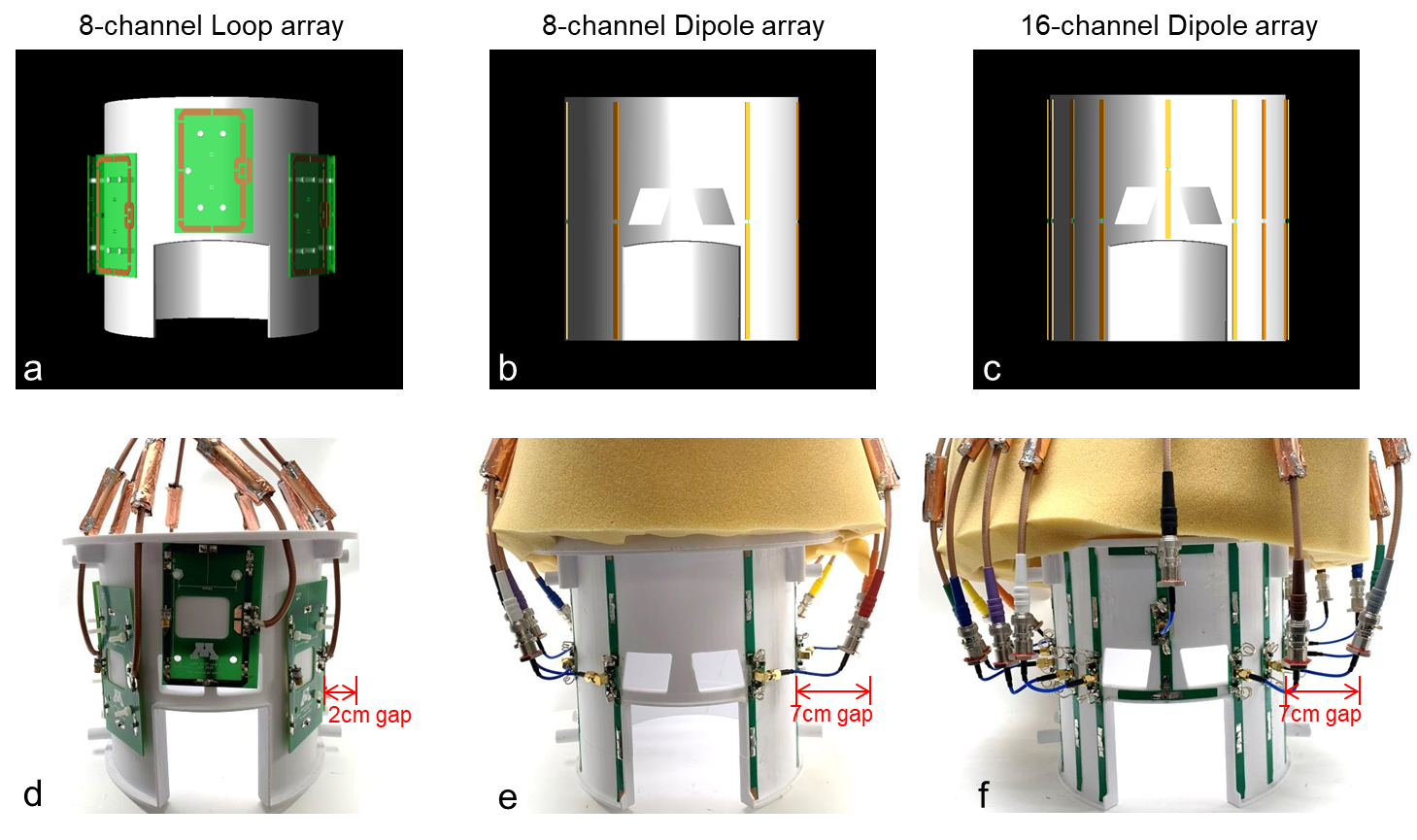
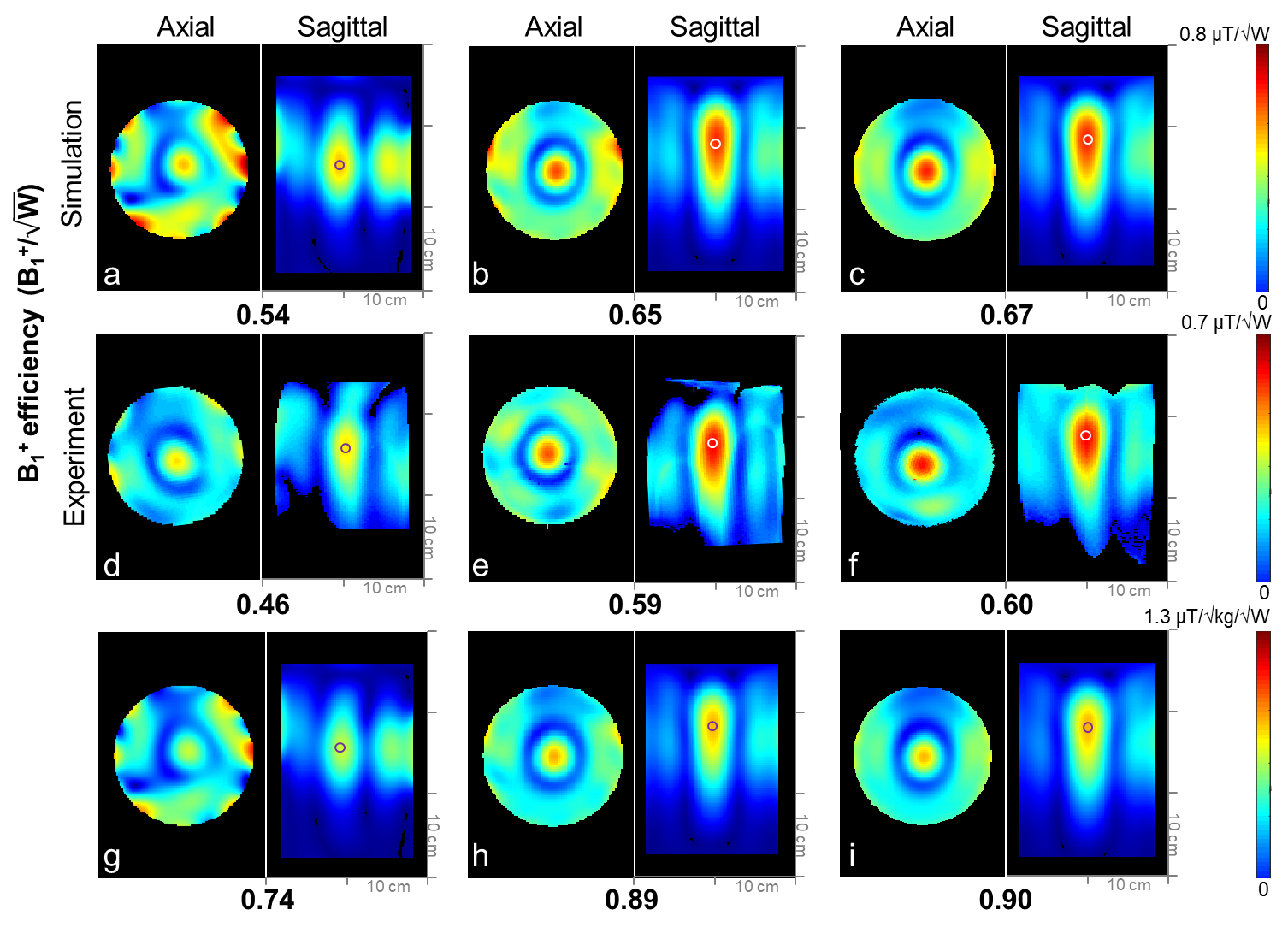
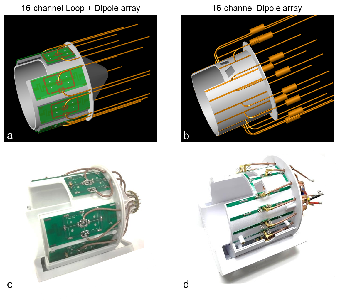
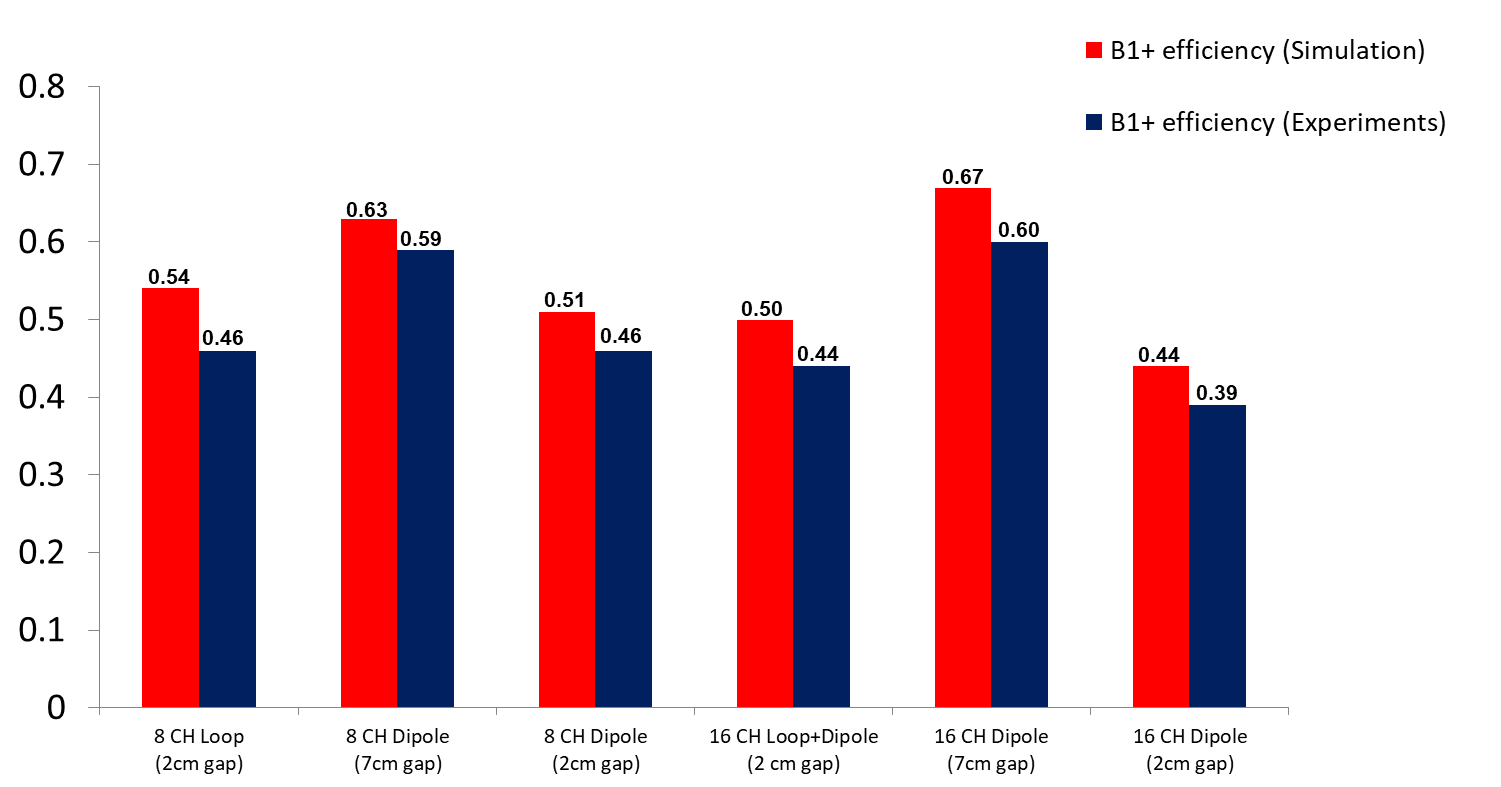
For the initial experiments a 7 cm distance (which is in practice an unrealistic distance) between the coaxial feed cables and dipoles for both the 8-channel dipole and the 16-channel dipole arrays was built and evaluated. We then modified the feed cable routing for realistic housings with a reduced distance of 2 cm between dipole and coaxial feed cable and compared the same 8- and 16-channel dipole arrays for the 2 cm gapped coaxial cable routing. Additionally we extended the comparison to include a previously developed 16-channel Loop+Dipole array combination with 2 cm coaxial cable routing[7]. Detailed 3D drawing and photographs of the 8-channel loop, 8-channel dipole, the 16-channel Loop+Dipole and the 16-channel dipole transceiver head arrays are shown in Fig. 1 and 3. All of the arrays have the same dimensions and were mounted on elliptic cylindrical formers with an inner diameter of 20 × 22 cm2 and length of 20 cm. The 8-channel loop, the 8-channel dipole and the 16-channel Loop+Dipole arrays have eight roughly equally spaced antenna elements. Lattice baluns for matching on all feed points were used to reduce sheath currents. The length of the dipole of the 16-channel Loop+Dipole is 18 cm with the fractionation of dipole. The EM simulation (XFdtd, REMCOM, State College, PA) was performed to calculate the B1+ field and the 10g specific absorption ratio (SAR). Experimental B1+ fields were obtained using an actual flip angle imaging (AFI) sequence for a cylindrical phantom (18 cm diameter and 30 cm long) with uniform electrical properties (σ = 0.6 S/m and εr = 49) at 10.5T [8, 9]. B1+ fields were calculated in MATLAB (Mathworks, Inc., Natick, MA, USA) and were normalized to 1 W for B1+ efficiency (B1+/√W). The B1+ efficiency and SAR efficiency (B1+/√10g SARpeak) were compared for the 8-channel loop, the 8-channel and 16-channel dipole with an impractical 7cm gap and a realistic but tighter 2cm gap between the coaxial cable setup and the antennas. The 16-channel Loop+Dipole array had an even tighter 2cm distance between the coaxial feed of the loop coils. The resulting B1+ and SAR efficiencies of all arrays were summarized in Table 1.Results and Discussion
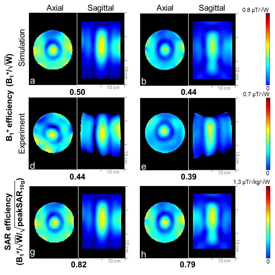
An excellent agreement between simulation and experiment (±10%) was achieved for the highest B1+ efficiency values. Fig. 2 shows B1+ efficiency of the 8-channel loop, the 8-channel dipole and the 16-channel dipole arrays with the 7cm gap coaxial cable setup. In Fig. 2d, 2e and 2f, the dipole type antenna (the 8-channel and 16-channel dipole arrays) shows ~23% higher B1+ efficiency compared to the loop type antenna (8-channel loop array) in the experiment. In Fig. 2f and 4e, however, the B1+ efficiency of the 16-channel dipole array with tight (2cm gap) coaxial setup arrays dropped further to 35% compared to the 7cm gap setup of the 16-channel dipole array. Then B1+ efficiency of the 16-channel dipole array was 27% higher with the larger 7cm gap setup and 13% lower with the tighter 2cm gap setup compared to the 16-channel Loop+Dipole array. The tight gap (2cm) among coaxial cables and dipoles for the practical human head imaging setup degraded the performance of the B1+ efficiency significantly. In Fig. 2i and 4h, SAR efficiency values were dropped 12% from the interference of coaxial cables and dipoles because SAR values also were decreased as B1+ efficiency values were decreased.Conclusion
We observed a reduction in B1+ efficiency for all head coil arrays presumably due to interaction between the coaxial feed cables and coil elements. The B1+ and SAR efficiency, particular for dipoles, dropped significantly for realistic cable routings due to interference between coaxial feed cables and the dipole leg. For the typically more lightly loaded head dipole type antennas a larger distance between the dipole and the coaxial feed cables is desired and leads to higher B1+ and SAR efficiency compared to both loop type arrays and loop-dipole combination arrays. This effect was not observed for our body dipole arrays [10] and we attribute this to the significant heavier subject loading of body dipole elements compared to head dipoles. Both 8 channel arrays had the best overall performance for realistic cable routes which we attribute to the improved overall element decoupling for the relatively light head loads.Acknowledgements
NIH-U01-EB025144, NIH-S10-RR029672, NIH- P41-EB027061 and NIH-P30-NS076408References
[1] G. Adriany, A. Gozubuyuk, E. Auerbach et al., “A 32 channel Transmit/Receive transmission line head array for 3D RF Shimming,” proceedings of the 15th scientific meeting, International Society for Magnetic Resonance in Medicine, Berlin, Germany, vol. 166, 2007.
[2] Z. Cao, J. Park, Z. H. Cho et al., “Numerical evaluation of image homogeneity, signal‐to‐noise ratio, and specific absorption rate for human brain imaging at 1.5, 3, 7, 10.5, and 14T in an 8‐channel transmit/receive array,” Journal of Magnetic Resonance Imaging, vol. 41, no. 5, pp. 1432-1439, 2015.
[3] J. H. Duyn, P. van Gelderen, T.-Q. Li et al., “High-field MRI of brain cortical substructure based on signal phase,” Proceedings of the National Academy of Sciences, vol. 104, no. 28, pp. 11796-11801, 2007.
[4] R. Lattanzi, G. C. Wiggins, B. Zhang et al., “Approaching ultimate intrinsic signal‐to‐noise ratio with loop and dipole antennas,” Magnetic resonance in medicine, vol. 79, no. 3, pp. 1789-1803, 2018.
[5] A. Raaijmakers, O. Ipek, D. W. Klomp et al., “Design of a radiative surface coil array element at 7 T: the single‐side adapted dipole antenna,” Magnetic resonance in medicine, vol. 66, no. 5, pp. 1488-1497, 2011.
[6] G. C. Wiggins, B. Zhang, R. Lattanzi et al., “The electric dipole array: an attempt to match the ideal current pattern for central SNR at 7 Tesla,” Proceedings of the 20th scientific meeting, International Society for Magnetic Resonance in Medicine, Melbourne, Australia, vol. 541, 2012.
[7] M. K. Woo, R. L. Lagore, L. DelaBarre et al., “A 16-channel transceiver loop+ dipole antennas head array for human head imaging at 10.5 T,” in Electromagnetics in Advanced Applications (ICEAA), 2017 International Conference on, Verona, Italy, 2017, pp. 1649-1652.
[8] B. Beck, K. Jenkins, J. Rocca et al., “Tissue‐equivalent phantoms for high frequencies,” Concepts in Magnetic Resonance Part B: Magnetic Resonance Engineering: An Educational Journal, vol. 20, no. 1, pp. 30-33, 2004.
[9] V. L. Yarnykh, “Actual flip‐angle imaging in the pulsed steady state: a method for rapid three‐dimensional mapping of the transmitted radiofrequency field,” Magnetic Resonance in Medicine: An Official Journal of the International Society for Magnetic Resonance in Medicine, vol. 57, no. 1, pp. 192-200, 2007.
[10] Erturk, M. A., X. P. Wu, Y. Eryaman, P. F. Van de Moortele, E. J. Auerbach, R. L. Lagore, L. DelaBarre, J. T. Vaughan, K. Ugurbil, G. Adriany and G. J. Metzger (2017). "Toward imaging the body at 10.5 tesla." Magnetic Resonance in Medicine 77(1): 434-443.
Figures