0745
An 8-CH Dipole Transceiver Array with 24-CH Loop Receiver Array for Non-Human Primate Head Imaging at 10.5T1Center for Magnetic Resonance Research, University of Minnesota, Minneapolis, MN, United States
Synopsis
In this work we developed an 8-CH dipole transceive with 24-channel loop receive array (for a total of 32 receive channels) for head imaging of anesthetized non-human primates at 10.5T. We demonstrate the benefits of receiving with both the dipole array and loop arrays to recapture SNR in deep brain structures and allow for accelerated acquisitions with near lossless parallel imaging performance up to R=3 in either AP or LR. Presented are diffusion and anatomical MR images acquired with this coil.
Introduction
In recent years, there has been a proliferation of 7T and higher human ultra-high field systems motivated by the fact that the higher SNR at UHF and contrast to noise (CNR) will permit anatomical, functional imaging and DTI with higher resolutions. These systems have enormous appeal to study non-human primates (NHP)[1-6].We previously developed an NHP head coil for 7T [7, 8] and reported preliminary results for an 8-CH dipole / 8-CH loop array at 10.5T [9]. These designs proved successful due to the SNR benefits of a close-fitting loop receive array in combination with a line element transmit array which benefit by being inherently decoupled. The combination of transceiver dipoles with receive loop arrays increases the number of decoupled receiver channels and is expected to optimize penetration and SNR for obtaining high resolutions of deep and sub-cortical structures [10-13].
The aim of this work was to build and evaluate an 8-channel dipole tranceiver and 24-channel loop receiver for NHP applications.
Methods
8-CH Dipole Transceiver ArrayThe dipole array used in this work (described in [9]) is used for transmit and receive and is interfaced to the system via an 8-CH T/R switch box with integrated preamplifiers (Gain = 20 dB, NF = 1.0 dB).
Two receive-only arrays are used:
8-CH Loop Receive Array (lower insert)
The lower loops are rectangular 5 x 10 cm in a 2 x 4 arrangement (Figure 2 top-right) constructed from six segments of 18 AWG silver-plated copper wire (SPCW) and mounted on a cylindrical surface 14.5 cm in diameter. Ceramic capacitors (100B series, ATC, USA) and variable capacitors (SGC3 series, Sprague-Goodman, USA) are used for segmentation, tuning, and matching. Preamplifiers are located in an 8-CH receive box and interconnected using a set of eight ¾ wavelength G_02232-09 (Huber+Suhner, Switzerland) coaxial cables.
16-CH Loop Receive Array (head cap)
Head cap loops are constructed on a close-fitting head cap former from 20 AWG SPCW and insulated with PTFE shrink tubing. Loops are ~37 mm in diameter and arranged in rows of 4-3-2-3-2 with an ear loop at each end (Figure 2: top-left). Loops are segmented 2-4 ways with a trimmer (Thin-Trim, Knowles-Johanson, UK) located opposite the feed for fine tuning. All ceramic capacitors are 0603 SMDs (Knowles-Syfer, UK). An 0807 SMD air-core inductor (CoilCraft, USA) and PIN diode (MA4P1250NM-1072T, MACOM, USA) were used for active loop detune (schematic in Figure 3). Each ear is encircled by a large receive loop which can be partially detached via a pair of non-magnetic, gold plated connectors (ODU, Germany). This simplifies coil setup on an NHP that has its head fixed in ear bars. Each loop is connected to a preamp via ~80 mm of 1.2 mm diameter low loss semi-rigid coaxial cable (UT-47-C-TP-LL, Carlisle IT, USA). Capacitor shortened sleeve baluns are placed on each coaxial cable to eliminate sheath currents induced by the transmitter.
Preamplifiers
WMA447A (WanTcom, USA)
|Zin| = 1.5Ω
NF = 0.45 dB
Gain = 28 dB
The preamp is mounted to a breakout/daughter board, which is mounted inverted to a motherboard. Both boards have an RF ground plane which the preamp is sandwiched between to provide E-field shielding from the transmitter. The preamp motherboard, which contains an output cable trap and bias tee, is 4 x 1.3 cm in size. The daughterboard and motherboard connect via low profile header/receptacles (BBL-103-G-E and SL-103-G-10, Samtec, USA).
Testing
Coils were evaluated using a 16-port VNA (ZNBT8, Rohde&Schwarz, Germany) then tested on a 10.5T MRI system (Siemens MAGNETOM, Germany). Intrinsic signal-to-noise maps were calculated from fully-relaxed proton-density weighted gradient echo images and a noise scan with flip angle correction via an AFI B1 map [14]. Parallel imaging performance was assessed with the g-factor for SENSE [15], using sensitivities calculated with ESPIRIT [16] from a GRE acquisition, and noise-correlation determined from a noise-only acquisition and reported as 1/g values. Theoretical 1D undersampling performance for oblique axial planes restricted to the NHP brain where evaluated for R={2,3,4,5}, and experimental g-factors for R=3 with GRE-EPI with AP phase-encoding was obtained. Mean and maximal g-factor for using the 98 percentile of the g-factor map are used.
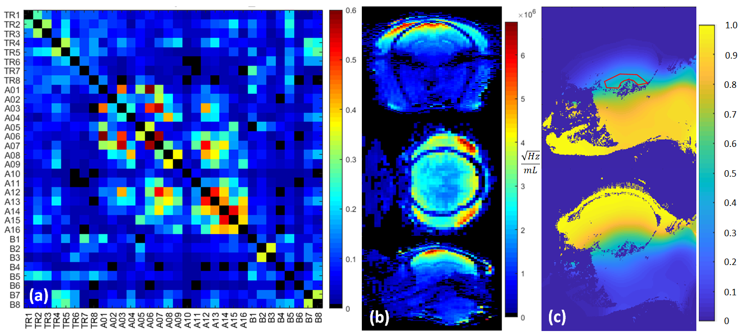
Results and Discussion
Noise correlation (Figure 3a) demonstrates acceptable crosstalk (<0.25) for most channels. SNR maps (Figure 3b) indicate a rapid fall off of signal as distance from the head cap receiver increases with greatest SNR in the scalp and six-fold lower SNR in deep brain structures. This motivated the development of the lower 8-CH receive insert and use of the dipole array as a transceiver which together contribute half of the overall SNR to the deep brain (Figure 3c). As demonstrated previously, loops and dipoles do not couple strongly nor produce split resonances. Theoretical parallel imaging performance is evaluated via 1/g-factor maps for a 90x90mm FOV over a depth of 50mm, and g-factor maps are shown for a representative slice for R=3, with AP and LR phase-encoding undersampling, respectively (Figure 4). For AP phase-encoding, 1/g-factor ~ 1 (for R=3), reflecting the arrangement of 5 loops front-to-back while for LR phase-encoding the 1/g-factor < 1 (for R=3) since there are 4 loops left-to-right. Application specific imaging results are shown in Figure 5.Acknowledgements
NIH R01 NS08118, P41EB027061, P30 NS076408, S10 RR029672, and University of Minnesota Udall center P50NS098573.
References
[1] Milham, M.P., et al., An Open Resource for Non-human Primate Imaging. Neuron, 2018. 100(1): p. 61-74 e2.
[2] Logothetis, N.K., et al., Ultra High Resolution fMRI in Monkeys with Implanted Coils. Journal of Neuroscience Methods, 2002.
[3] Pfeuffer, J., et al., Anatomical and functional MR imaging in the macaque monkey using a vertical large-bore 7 Tesla setup. Magn Reson Imaging, 2004. 22(10): p. 1343-59.
[4] Gilbert, K.M., et al., Optimized parallel transmit and receive radiofrequency coil for ultrahigh-field MRI of monkeys. Neuroimage, 2016. 125: p. 153-161.
[5] Goense, J., N.K. Logothetis, and H. Merkle, Flexible, phase-matched, linear receive arrays for high-field MRI in monkeys. Magn Reson Imaging, 2010. 28(8): p. 1183-91.
[6] Janssens, T., et al., An implanted 8-channel array coil for high-resolution macaque MRI at 3T. Neuroimage, 2012. 62(3): p. 1529-36.
[7] Adriany, G., et al., A 21 channel Transceiver Array for Non-human Primate Applications at 7 Tesla. Proc. 18th ISMRM, 2010: p. 1490.
[8] Zitella, L.M., et al., In Vivo 7T MRI of the Non-Human Primate Brainstem. PloS one, 2015. 10(5): p. e0127049.
[9] Lagore R.L., et al., An 8 Channel Dipole Transmit Array and 8 Channel Receive Array for Head Imaging of Non-Human Primates at 10.5T. Proc. 27th ISMRM, 2018: p. 1747.
[10] Raaijmakers, A.J., et al., Design of a radiative surface coil array element at 7 T: the single-side adapted dipole antenna. Magnetic resonance in medicine : official journal of the Society of Magnetic Resonance in Medicine / Society of Magnetic Resonance in Medicine, 2011. 66(5): p. 1488-97.
[11] Erturk, M.A., et al., Toward imaging the body at 10.5 tesla. Magnetic Resonance in Medicine, 2017. 77(1): p. 434-443.
[12] Erturk, M.A., et al., A 16-channel combined loop-dipole transceiver array for 7 Tesla body MRI. Magn Reson Med, 2016.
[13] Woo, M.K., et al., A 16-channel Transceiver Loop plus Dipole Antennas Head Array for Human Head Imaging at 10.5T. 2017 International Conference on Electromagnetics in Advanced Applications (Iceaa), 2017: p. 1649-1652.
[14] Yarnykh V.L., Actual flip-angle imaging in the pulsed steady state: A method for rapid three-dimensional mapping of the transmitted radiofrequency field. Magn Reson Med, 2006. 57(1): p. 192-200.
[15] Pruessmann, K.P., et al., SENSE: sensitivity encoding for fast MRI. Magn Reson Med, 1999. 42(5): p. 952-62.
[16] Uecker, M., et al., ESPIRiT--an eigenvalue approach to autocalibrating parallel MRI: where SENSE meets GRAPPA. Magn Reson Med, 2014. 71(3): p. 990-1001.
Figures