0675
Consistency in human and machine-learning based scan-planes for clinical knee MRI planning
Chitresh Bhushan1, Dattesh D. Shanbhag2, Andre Maximo3, Uday Patil2, Radhika Madhavan1, Matthew Frick4, Kimberly K. Amrami4, Desmond Teck Beng yeo1, and Thomas Foo1
1GE Research, Niskayuna, NY, United States, 2GE Healthcare, Bengaluru, India, 3GE Healthcare, Rio de Janeiro, Brazil, 4Mayo Clinic, Rochester, MN, United States
1GE Research, Niskayuna, NY, United States, 2GE Healthcare, Bengaluru, India, 3GE Healthcare, Rio de Janeiro, Brazil, 4Mayo Clinic, Rochester, MN, United States
Synopsis
We evaluate the consistency and clinical applicability of our automated deep-learning based intelligent slice placement (ISP) approach for knee scan planning. We use 146 clinical knee exams that were retrospectively selected to have anatomically consistent scan planning along with manual-marking from in-house radiologist to access the variability across MR technicians. The results indicate that our automated ISP approach has better consistency than the variability seen across MR technicians for coronal and sagittal knee scan planning, indicating promising clinical applicability of our automated ISP approach.
INTRODUCTION
Quality of diagnostic MR images in clinical practice is heavily dependent on consistency in anatomical definition of the scan-planes used for the scan planning. It is well known that even with well-trained technicians there are inter-technician variations in clinical scan planning resulting into inconsistent and irreproducible image quality1. Often these variations are driven by difference in preferences of each technician (or organization) but are acceptable in clinical practice. In this study, we explore variability of our automated deep-learning (DL) based intelligent slice placement (ISP) approach as compared to the inter-technician variability for the task of clinical knee scan planning.METHODS
Data: In this study, we use two scan-planes that are routinely used in clinical practice: a coronal plane aligned to posterior end of Femoral condyles and sagittal plane aligned to inner lateral side of femoral condyles typically used for scanning anterior cruciate ligament (ACL). To access the variability in human technicians, we use exams from a clinical site over 6-month period as scanned by several technicians (patient age range: 4-92 yrs; GE 3T Discovery MR 750w, GE Signa HDxt 1.5T; several coils) and retrospectively selected 146 exams that were considered to have anatomically consistent scan planning by the reading radiologist. To get a second scan prescription for each case, we used markings from an in-house expert, where scan-planes were marked on localizer images following the same anatomical definitions as the clinical-scans (high-resolution images were available for reference whenever needed). All studies were approved by the appropriate IRB.Pre-trained DL-models: Our ISP approach uses pre-trained DL-models to estimate both coronal and sagittal scan plan prescriptions from 2D tri-planar localizer images (2D SSFSE, TE/TR = 80 ms/1120 ms, FA = 90°, in-plane resolution = 0.55 mm x 0.55 mm, Slice Thickness = 10 mm, matrix = 512x512, slices = 5). These DL-models were derived from previous work2 and uses 3D u-net to predict segmentations for scan-planes from input tri-planar localizer images. The DL-models for ISP were trained with knee dataset from multiple sites, multiple MRI scanners with different coil configurations (>20,000 localizer images; GE 3T Discovery MR 750w, GE Signa HDxt 1.5T, GE 1.5T Optima 450w; 16-/18-channel TR Knee coil, GEM Flex coil). The pre-trained DL-models were used to predict scan-plane segmentations for each clinical exam, which were converted to clinical prescription by a simple plane fitting. Note that the DL-models were pre-trained with a knee dataset that is separate from the clinical data for this study.
Consistency Analysis: For each scan-plane of each clinical case, we obtained three different geometric planes: first, as used by clinical MR technician (Tech); second manually marked by in-house expert (Man-Mark); and third predicted by our DL-based ISP approach. Figure 1 shows an example of the three different scan plannings for one case. As the second prescription (Man-Mark) is done by same person, it can be used as reference for measuring the inter-technician variation. Hence, our evaluations are based on the spread of angle-differences we observe between pair of different the scan-planning approaches. We compute signed angle difference between scan-planes obtained by Man-Mark and technician (Man-Mark-vs-Tech) across all cases to obtain the inter-technician variation. Similarly, we compute signed angle difference between scan-planning obtained DL-based ISP approach and Tech (DL-vs-Tech) to evaluate the consistency of the DL-approach with clinical prescriptions.
RESULTS and DISCUSSION
Fig-2 shows the angle differences for both scan-planes across the population as box plots in unit of degrees (an angle difference of close to zero indicates very similar scan-planes). If all technicians agreed in their prescription Man-Mark-vs-Tech would have zero variance, and mean difference would indicate bias between Man-Mark and technicians. For coronal plane, std-dev. (and extents of whisker) for DL-vs-Tech is very similar to Man-Mark-vs-Tech, indicating similar consistency of our DL-based ISP approach to the variation seen across humans for the prescription. This consistency can also be explained by the fact that the coronal prescription primarily dependent on finding the plane passing through the posterior ends of condyles, which can be easily located on localizer images, resulting into lower variation across approaches. Coronal prescription shows lower absolute mean angle difference for Man-Mark-vs-Tech, however the difference was not statistically significant (p-value=0.61 for one-sided Mann-Whitney U test on less than absolute angle differences).For sagittal scan-planes, we notice that std-dev. (and extents of whisker) for DL-vs-Tech is substantially smaller than Man-Mark-vs-Tech in fig.2, which indicates significantly better consistency with DL-based approach despite slightly larger bias (p-value=1.1e-5 for one-sided Mann-Whitney U test on less than absolute angle differences). Since sagittal plane definition is dependent on localization of ACL, which is difficult to visualize on localizer images, technicians generally use a surrogate structure such as inner femoral condyle for planning. This requires intricate understanding of relative positioning of different anatomical structures for good planning, where DL-based approach can provide better consistency and smaller room for errors.
Conclusion
Anatomical consistency in planning of scan-planes for knee MRI is key to diagnostic reliability and best outcome for patients. Our automated deep-learning based intelligent slice placement (ISP) approach shows significantly better anatomical consistency than variation observed across different MR technicians for knee scan planning, suggesting promising clinical applicability.Acknowledgements
No acknowledgement found.References
- Heese et al., Consistency in automated versus manual definition of MRI scan volume orientations of the human heart. In Proceedings of ISMRM 2009, Honolulu, Hawaii, USA, p. 4681
- Shanbhag DD et.al. A generalized deep learning framework for multi-landmark intelligent slice placement using standard tri-planar 2D localizers. In Proceedings of ISMRM 2019, Montreal, Canada, p. 670.
Figures
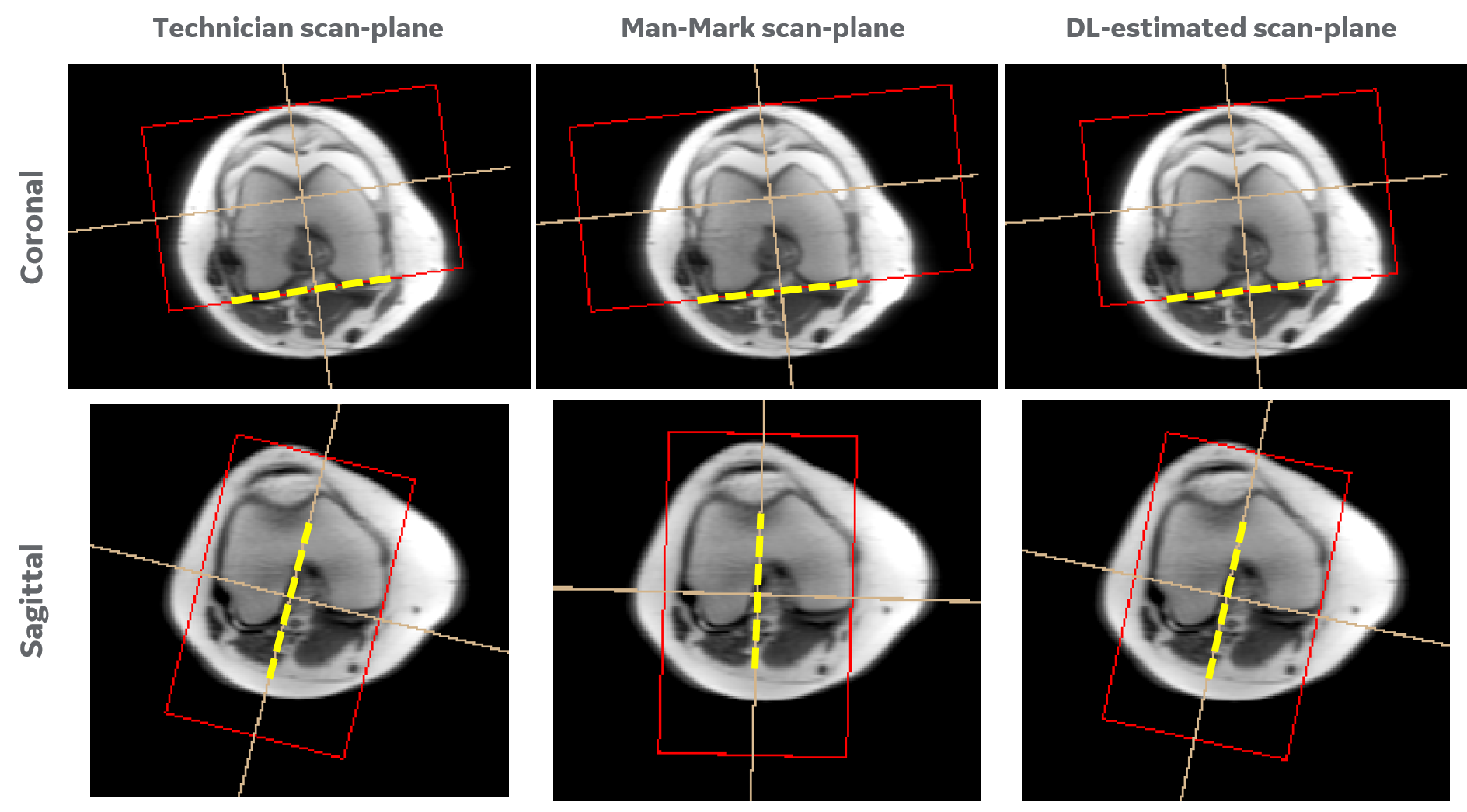
Figure 1: Examples of knee scan
plannings. Different (top-row) coronal and (bottom-row) sagittal scan-planes are shown, which are obtained from (left)
Technician, (center) manually marked, and (right) our deep-learning (DL)
approach. All scan-plane examples are shown overlaid over corresponding
localizer images and the principal planes for each is highlighted in
bold-dotted yellow line. Although these scan-plane may look similar when
visualized side-by-side, they are different by 2-18 degrees in orientation.
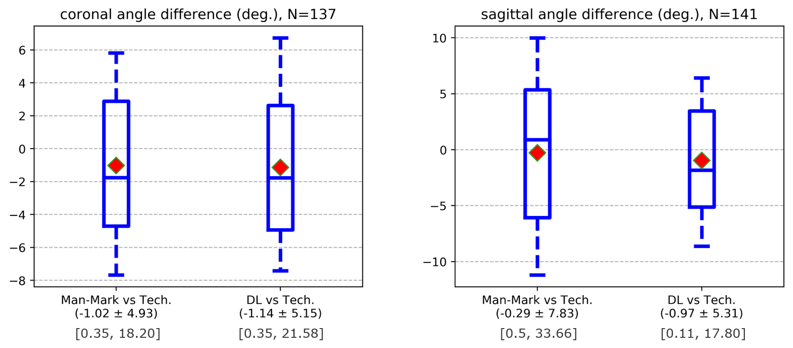
Figure 2: Angle differences between for (left) coronal and (right)
sagittal scan planning are plotted as box-plots. The box extends from 25th to 75th
percentile with whiskers extending from 5th to 95th
percentile. Red diamond marker indicates mean of the angle difference. Second
line of x-axis label reports the mean and std-dev, while third line reports the
min-max range.