0653
Optical Field Probes for MRI1Danish Research Centre for Magnetic Resonance, Centre for Functional and Diagnostic Imaging and Research, Copenhagen University Hospital Hvidovre, Hvidovre, Denmark, 2Quantop, Niels Bohr Institute, University of Copenhagen, Copenhagen, Denmark, 3School of Physics and Astronomy, University of Nottingham, Nottingham, United Kingdom, 4Department of Health Technology, Technical University of Denmark, Kgs. Lyngby, Denmark
Synopsis
A novel optical field probe is described for the precision measurement of high magnetic fields. The advantages over traditional field probes are two-fold. First, there is no electromagnetic interference with the other parts of the MRI system such as the RF coil. Secondly, the setup allows for a continuous and long readout of the magnetic field during an MRI sequence, where traditional NMR probes typically operate in a pulsed mode.
INTRODUCTION
NMR field probes have shown to be highly successful for the correction of gradient infidelities in MRI systems [1,2]. With this approach, an array of small NMR probes is used either consecutively or in conjunction with patient scanning to provide an improved sensing of the used k-space encoding, leading to either reconstruction based or real-time B0 field correction. Traditional field probes however can show electromagnetic interference with the default RF coils, due to presence of metal, resonant structures and cables. Also, NMR probes (like any NMR measurement) can only be used in a pulsed mode.A viable alternative for accurate magnetic field monitoring could be found in optical magnetometers, which can provide extremely high sensitivity for measuring magnetic fields [3] but have so far not been explored in high magnetic fields such as used for MRI. The use of optical magnetometers in MRI could provide not only a sensitive, but also a continuous measure of the gradient fields, and eliminate electromagnetic coupling to other parts of the setup.
In this work we explore the use of an optical magnetometer in high magnetic fields for MRI gradient mapping.
METHODS
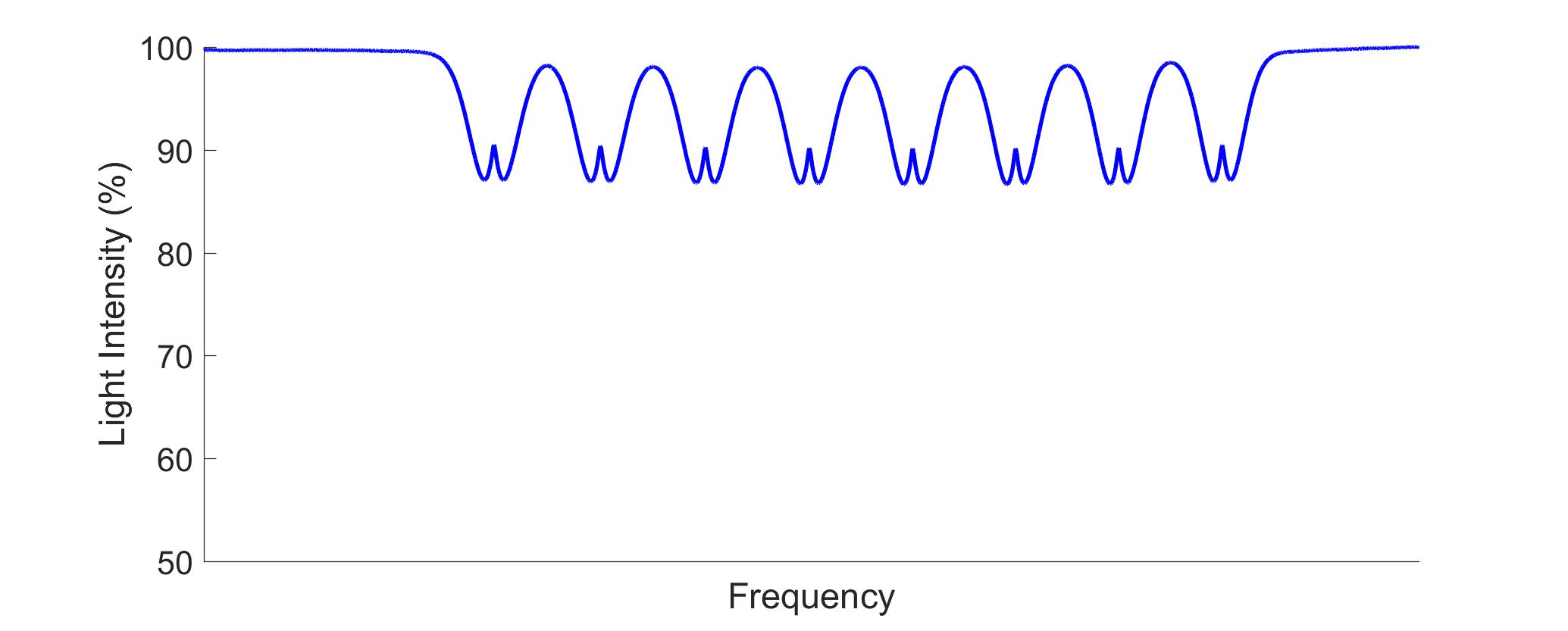
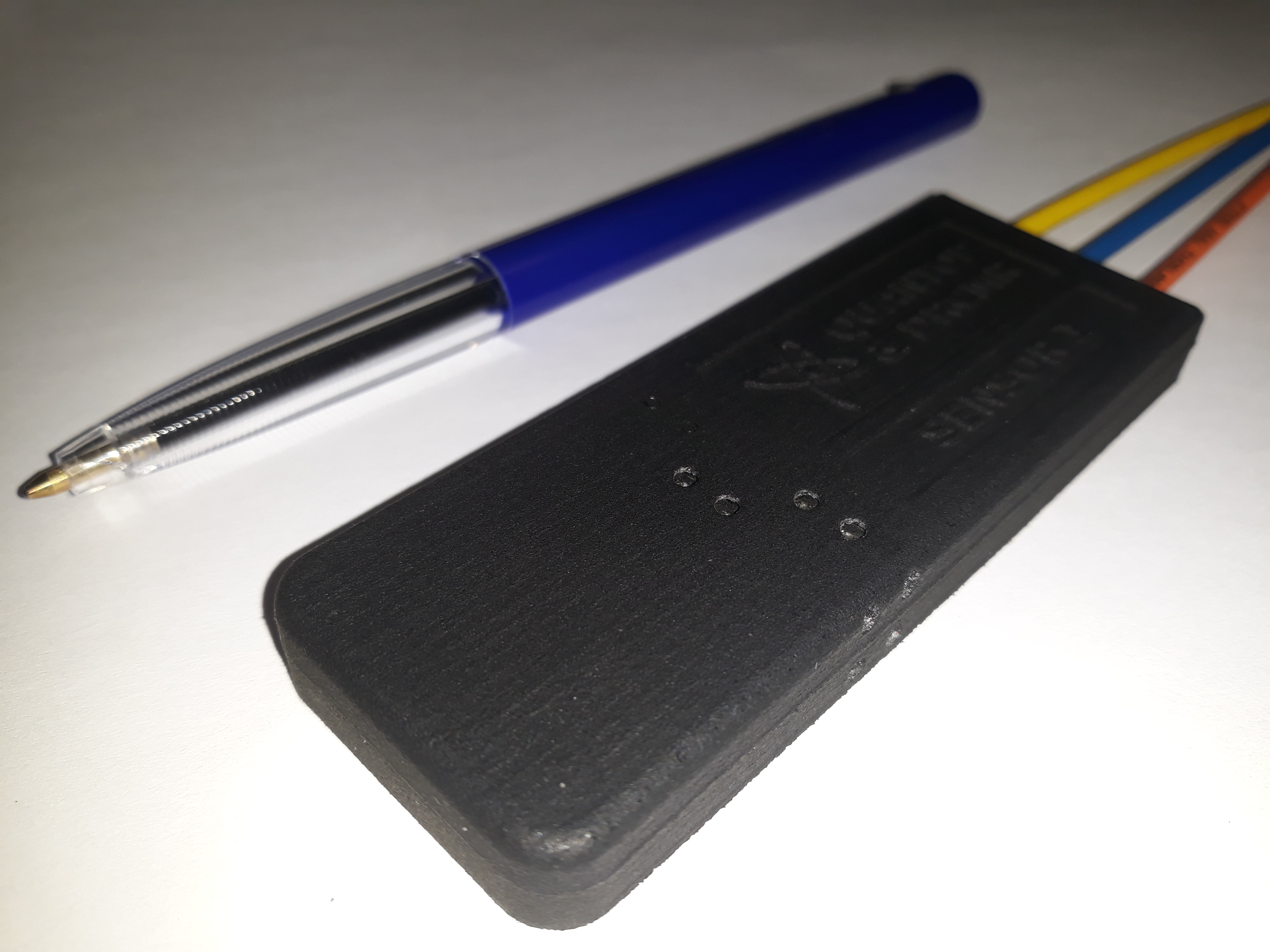
We designed a precise optical magnetometer based on laser spectroscopy in cesium gas. The setup is shown in figure 1. The optical transition in cesium from the ground state 62S1/2, F = 4, mF = 4, to the excited state 62P3/2, F = 5, mF = 5 has a linear frequency shift of 14 GHz/T. A part of the optical spectrum at 7 T is shown in figure 2. By continuously tracking this optical resonance frequency, we extracted the magnetic field strength over time. A reference probe is used outside the MRI scanner to stabilize the laser frequency using an electro-optic modulator (EOM-0). During an MR sequence, the field at the probe changes on the order of +/- 10 mT. This corresponds to +/- 140 MHz of optical frequency shift. Using a feedback to another electro-optic modulator (EOM-1) the upper sideband is locked such that it tracks the optical resonance and allows for a continuous magnetic field readout.Most of the optical equipment such as the laser (at 852 nm) are located outside of the MRI scanner, and the optical setup for the precision laser spectroscopy is located in the MR bore and connected with fiber optic cables. The optics are integrated in a 3D printed holder of 90x33x10 mm3 and as such the probe is fully metal free, except for a tiny liquid cesium droplet. The probe is shown in figure 3. The blue fiber delivers the light, the orange fiber takes it back to a photodetector, and the yellow fiber is used for a high-power (811 nm) laser beam that heats the vapor cell, in order to improve the absorption signal from the cesium gas, thereby increasing sensitivity.
RESULTS
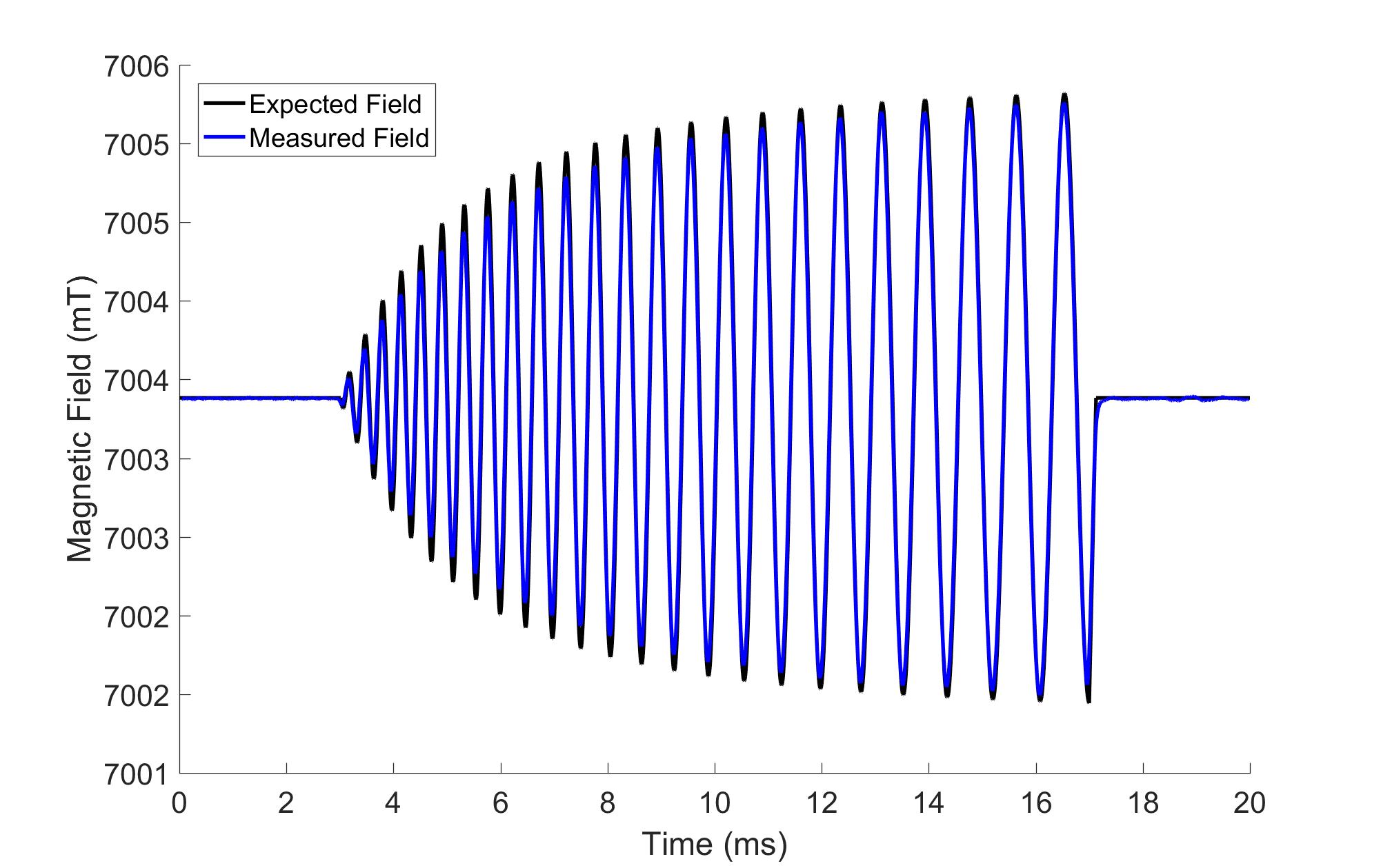
Gradient trajectories were mapped on a 7 Tesla system (Achieva, Philips, Best, The Netherlands) along the z-axis. A center-out single shot spiral waveform (14 ms, max gradient 19.4 mT/m and max slew rate 187 mT/m/ms) is shown in figure 4. An echo planar spectroscopic imaging waveform (406 ms, max gradient 20.9 mT/m and max slew rate 100 mT/m/ms) is shown in figure 5. Both were recorded by tracking the optical resonance using a digital oscilloscope (5 MS/s) and compared to the nominal waveforms that were used as input to the gradient amplifier system. The data where smoothed over 250 datapoint, giving a final bandwidth of 10 kHz, for the measurements. Notice that the sensitivity of the optical field probes is stable throughout the whole readout and does not lead to a compromise in detecting longer gradients.DISCUSSION
The tracking of the optical resonance resulted in a high-quality measurements of the gradient fields during MRI sequences. This could allow for the continuous and uncomplicated use of field probes during clinical exams as the optical field probes allow for a continuous readout and show no interaction with the RF system. Even at maximum gradient switching rates, the tracking was fast enough to follow the shift of the optical resonance. Further improvement of the sensitivity and stability of the setup are expected from improved control of the laser stability and improvements in the optical resonance linewidth, as well as an extension of the system with more probes, in order to reach a high accuracy continuous tracking system for magnetic field monitoring in MRI.The system is easily reconfigured to be used at different field strengths, like 1.5 T or 3 T.
CONCLUSION
Here we show first results of an optical magnetometer in an ultra-high magnetic field. Feedback tracking of an optical resonance of cesium allows for measurement of the gradient waveforms as played out during typical MRI experiments, and provides a continuous and coupling-free alternative to traditional NMR field probes.Acknowledgements
This work was supported by the Danish Quantum Innovation Center (QUBIZ)/Innovation Fund Denmark and the Quantum Technology Flagship project MACQSIMAL (820393)/European Union. The 7T scanner was donated by the Danish Agency for Science, Technology and Innovation grant no. 0601-01370B, and The John and Birthe Meyer Foundation.References
1. De Zanche, Barmet, Nordmeyer-Massner, Pruessmann “NMR probes for measuring magnetic fields and field dynamics in MR systems” MRM 60(1)176 2008
2. Barmet, De Zanche, Pruessmann, “Spatiotemporal magnetic field monitoring for MR”, MRM 60(1)187 2008
3. Budker, D., Romalis, M. Optical magnetometry. Nature Phys 3, 227–234 (2007) doi:10.1038/nphys566
Figures