0618
Multi-frequency wave-encoding (mf-wave) on gradients and multi-coil shim-array hardware for highly accelerated acquisition1State Key Laboratory of Modern Optical Instrumentation, College of Optical Science and Engineering, Zhejiang University, Hangzhou, China, 2Department of Radiology, A.A. Martinos Center for Biomedical Imaging, Massachusetts General Hospital, Charlestown, MA, United States, 3Harvard Medical School, Boston, MA, United States, 4Massachusetts Institute of Technology, Harvard-MIT Health Sciences and Technology, Cambridge, MA, United States
Synopsis
Wave-CAIPI is a parallel imaging technique that can provide high accelerations with negligible g-factor and artifact penalties. However, gradient amplitude & slew rate limits impose a limitation on the amount of wave-encoding and hence the acceleration capability of this technique. In this study, we propose a multi-frequency wave-encoding method (mf-wave) that uses both the gradients and a combined RF and B0 shim array (32-channel) to perform wave-encoding simultaneously and synergistically at different wave frequencies during the acquisition. We demonstrate that mf-wave can enable ~20-fold acceleration with an acceptable g-factor noise penalty at 3T in vivo.
Introduction
The application of sinusoidal encoding during data acquisition was first proposed in Bunched Phase Encoding1 with Gy sinusoidal encoding, which was then extended to Gy and Gz sinusoidal encodings with a quarter-cycle offset toMethod
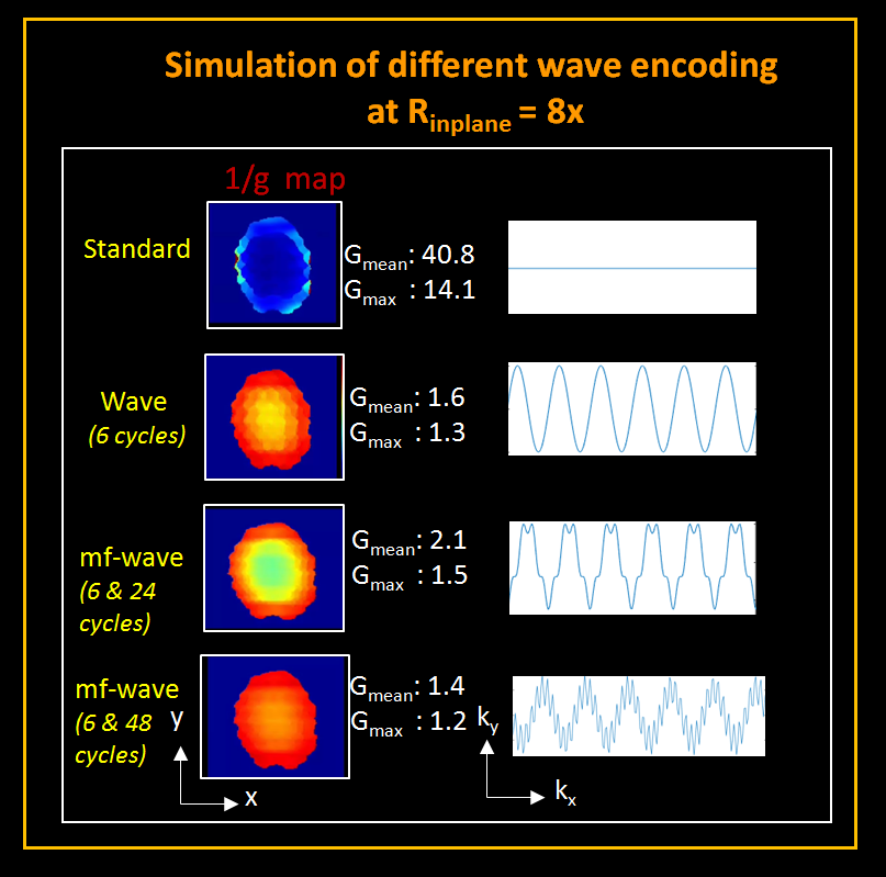
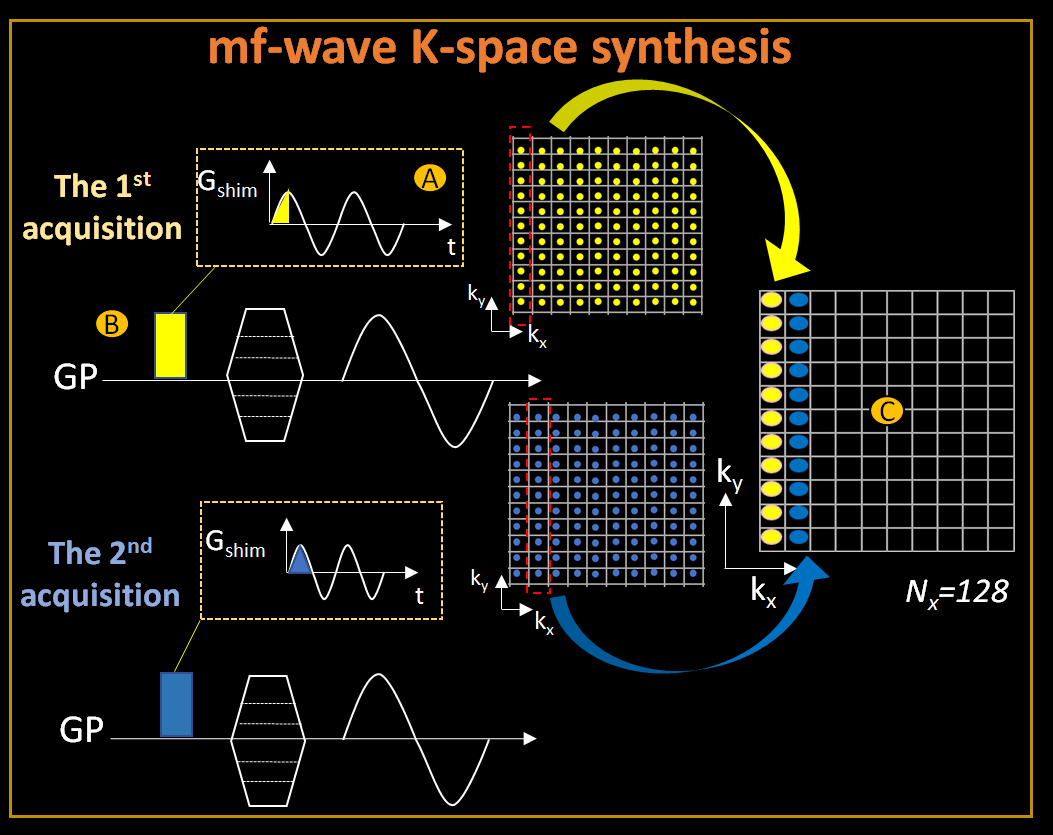
Theory:Fig1.A shows the hardware for generating the time-varying field needed for mf-wave-encoding. Fig1.B shows the sequence diagram for mf-wave where wave encodings are performed on both the gradients and shim array at different frequencies. Fig1.C shows the resulting k-space trajectories in both 2D and 3D/SMS acquisitions. Here slow-frequency wave-encoding is applied on the gradient hardware to provide large k-space wave modulation while high-frequency wave-encoding is performed with the shim array to further broaden the k-space coverage of this modulation. The slow frequency was chosen for the gradients as it works well with the slew and
Image reconstruction:
We generalized the forward-model of the voxel-spreading effects along the readout direction in wave-encoding from Bilgic et al 2 to mf-wave-encoding as:
$$W = F^{-1}(F\odot{E})m$$
Where $$$W$$$ is the vector along readout of the voxel-spreading image at the location $$$(y,z)$$$, $$$F$$$ is the 1D discrete Fourier transform matrix and $$$F^{-1}$$$ is the 1D inverse Fourier transform matrix, $$$E$$$ is a spatial-varying encoding matrix and $$$m$$$ is the corresponding row of the image data to be reconstructed at location $$$(y,z)$$$. Analogous to conventional wave-CAIPI reconstruction, this formulation makes the reconstruction process separable in the phase-encoding direction for mf-wave-encoding, thus allowing each set of collapsed $$$(y,z)$$$ rows to be solved independently, using e.g. lsqr in MATLAB. G-factor can also be calculated analogously.
In-vivo experiments
MATLAB’s quadprog function was used to find optimal shim currents for generating a close approximation to the desired wave encoding field, subject to practical current constraints (The chosen maximum of Imax= 8A per channel, while beyond the capabilities of the existing 32ch coil (4A max), could be realized in future designs using thicker wiring). The fields generated from this calculation are used in our g-factor simulation for optimizing the mf-wave-encoding.We are currently modifying our shim amplifier controller to
The imaging parameters were: GRE acquisition, FOV = 220x220x150 mm; resolution = 1.7x1.7x2 mm, TR/TE = 50/30ms, BW = 100Hz, FA = 18°,10ms readout. For gradient-wave-encoding, 6-cycles were employed with Gmax = 7mT/m and Smax = 150 T/m/s. For shim-wave-encoding, an approximately linear shim field was generated to approximate cos(wt)x and cos(wt)z modulations (48 cycles, 4.8kHz). A 6x readout oversampling was used to increase FOVx and capture the voxel spreading effects.
Results
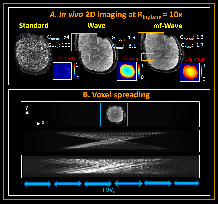
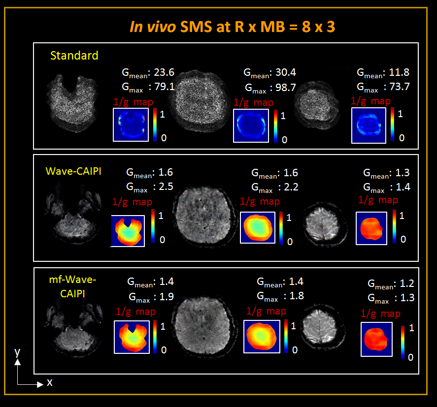
Figure 4 shows the reconstructions and corresponding 1/g factor maps of the acquired in-vivo 2D data at Rinplane =10-fold. At this extreme acceleration, the standard acquisition produces an unusable image, while wave-encoding produces images with substantial noise. The use of mf-wave-encoding produces images with significantly less noise, at a maximum g-factor that is ~2x lower than with wave-encoding.Figure 5 shows the reconstructions and corresponding 1/g factor maps of the acquired in-vivo SMS data at Rinplane x MB =8 x 3. Again, the images from the standard acquisition are unusable. Here wave-CAIPI provides large improvements, but still results in poor reconstruction, while mf-wave further improves upon this, with some artifacts remaining likely from minor deviations in the encoded field vs. theoretical field used in the reconstruction.
Discussion and Conclusion
mf-wave-encoding extends the wave-encoding technique to simultaneous wave-encoding on both gradients and multi-coil shim hardware. Preliminary exploration in this direction so far has shown promising results that point to the potential for significant increases in acceleration capability using this approach, with further optimization and dynamic experiments planned for future work. A further extension to include additional hardware components such as non-linear shim encoding gradients is also feasible and could potentially provide even further acceleration capability.Acknowledgements
This work is supported in part by the National Natural Science Foundation of China (No: U1809204, 61525106, 61427807, 61701436), by the National Key Technology Research and Development Program of China (No: 2017YFE0104000, 2016YFC1300302), and by Shenzhen Innovation Funding (No: JCYJ20170818164343304, JCYJ20170816172431715), by NIH R01EB019437, R01EB020613, R01 MH116173, U01EB025162 and NIH NIBIB R00EB021349. Jinmin Xu was supported by the China Scholarship Council for 2 years at Massachusetts General Hospital.
References
- Moriguchi, Hisamoto, and Jeffrey L. Duerk. "Bunched phase encoding (BPE): a new fast data acquisition method in MRI." Magnetic Resonance in Medicine: An Official Journal of the International Society for Magnetic Resonance in Medicine 55.3 (2006): 633-648.
- Bilgic, Berkin, et al. "Wave-CAIPI for highly accelerated 3D imaging." Magnetic resonance in medicine 73.6 (2015): 2152-2162
- Wang, Haifeng, et al. "Fast rotary nonlinear spatial acquisition (FRONSAC) imaging." Magnetic resonance in medicine 75.3 (2016): 1154-1165.
- Scheffler, Klaus, et al. "Spread‐spectrum magnetic resonance imaging." Magnetic resonance in medicine 82.3 (2019): 877-885.
- Stockmann, Jason P., et al. "A 32‐channel combined RF and B0 shim array for 3T brain imaging." Magnetic resonance in medicine 75.1 (2016): 441-451.
Figures
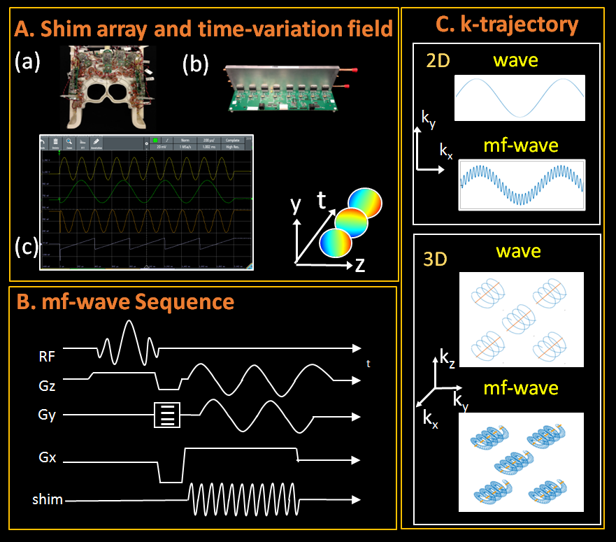
Figure 1: A. (a) shim array (b) amplifier hardware (c) oscilloscope trace showing 2ms example pulses on four DAC output channels driven by SPI-bus from FPGA (5 kHz sine, 2 kHz sine, phase-shifted 5 kHz sine, and ramp); waveforms will be used to drive shim amplifiers in future experiments. B. The mf-wave sequence based on wave-CAIPI sequence with extra shim encoding. C. The k-space trajectory in both 2D (top) and 3D (bottom) acquisition of wave and mf-wave encoding. With multi-frequency encoding, the wave trajectory can be further broadened leading to better coverage of k-space.