0613
Improvements in flip-angle uniformization at 7 Tesla using an integrated RF/B0 shim array coil and composite pulses1Martinos Center for Biomedical Imaging, Massachusetts General Hospital, Charlestown, MA, United States, 2Harvard Medical School, Boston, MA, United States
Synopsis
We compare the RF/B0 shim array composite pulses of Rudrapatna [1] to kT-point and spoke pulses for flip-angle (FA) uniformization using a birdcage coil at 7T. Using 3 kT-points, it is possible to obtained highly uniform flip-angle distributions in the brain within 3ms, as long as the kT-points locations are optimized. The RF/B0 shim array pulses perform less well than this optimized 3-kT-points strategy for non-selective flip-angle mitigation, but better than optimized 3-spoke pulses for flip-angle mitigation in a slice. The DOFs provided by shim array coils could prove invaluable for integrated B0 shimming and flip-angle uniformization at 7T.
Introduction
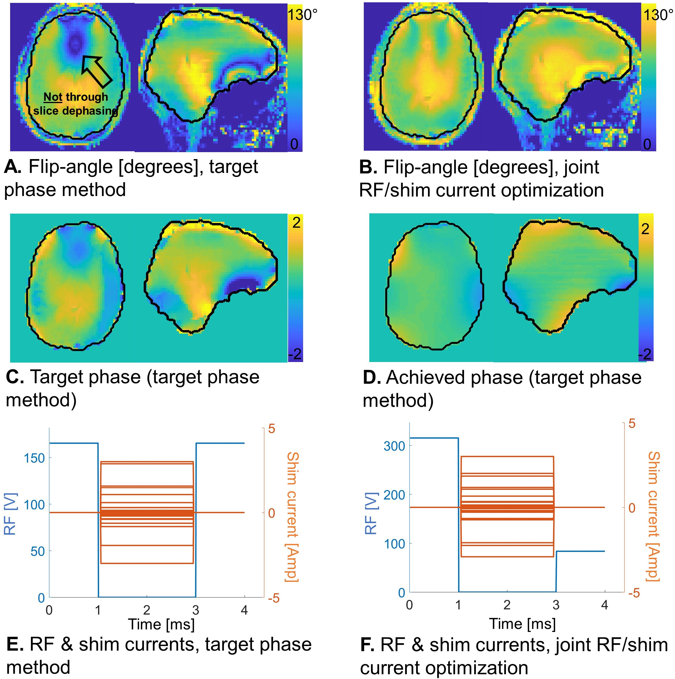
Rudrapatna et al [1] proposed a composite pulse approach that leverages the additional degrees-of-freedom provided by multi-coil B0 shim arrays (SA) in order to create uniform flip-angle excitations at 7T. The approach interleaves RF sub-pulses (rect for non-selective, sinc for slice-selective) and periods during which the shim-array is driven alone thus dephasing spins by different amounts in different regions of the field-of-excitation. They show that the ideal target phase pattern between the RF sub-pulses of a two-subpulse experiment (RF-SA-RF) can be derived analytically. Thus, they drive the SA so as to best approach this distribution. We show here that the RF-SA-RF experiment cannot yield inversion pulses, and that an RF-SA-RF-SA-RF (three sub-pulses) excitation must be used instead. In this case, an analytical expression for the target phase does not exist, the problem is instead cast as a joint optimization of the RF sub-pulse weights and shim currents. We implement this approach in a realistic head phantom and compare the performance of the RF/B0 shim array composite pulses to kT-points [4] and spoke [5] pulses for non-selective and slice-selective FA uniformization at 7T, respectively.Methods
Shim array: We use a 7T B0 shim array with 31 loops supporting both RF and DC current (“AC/DC” coil) patterned on a close-fitting helmet. The B0-field maps (Hz/Amp) of all channels were measured in lengthy scans in a silicone-oil phantom using the vendor-provided field-mapping sequence (2-mm iso., dual-echo, ΔTE=1.02ms). These maps are independent of the load and need to be acquired only once. RF transmission is by a birdcage coil.Pulse optimization: We cast the RF/B0 shim array pulse design as an optimization problem. Specifically, the forward model is a Bloch simulation in the spinor domain [3]. We jointly optimize the RF sub-pulse weights and shim currents subject to maximum RF amplitude (400V), maximum shim current (3Amp per channel) and maximum total current (30Amp) hard constraints using Matlab’s fmincon. We constrain the phase created by the SA between RF sub-pulses to below 100Hz in order to avoid large rotations of the magnetization that may lead to local minima. We initialize the pulse design using manual (first RF set to the target flip-angle, all shim currents to zero) and random initial guesses.
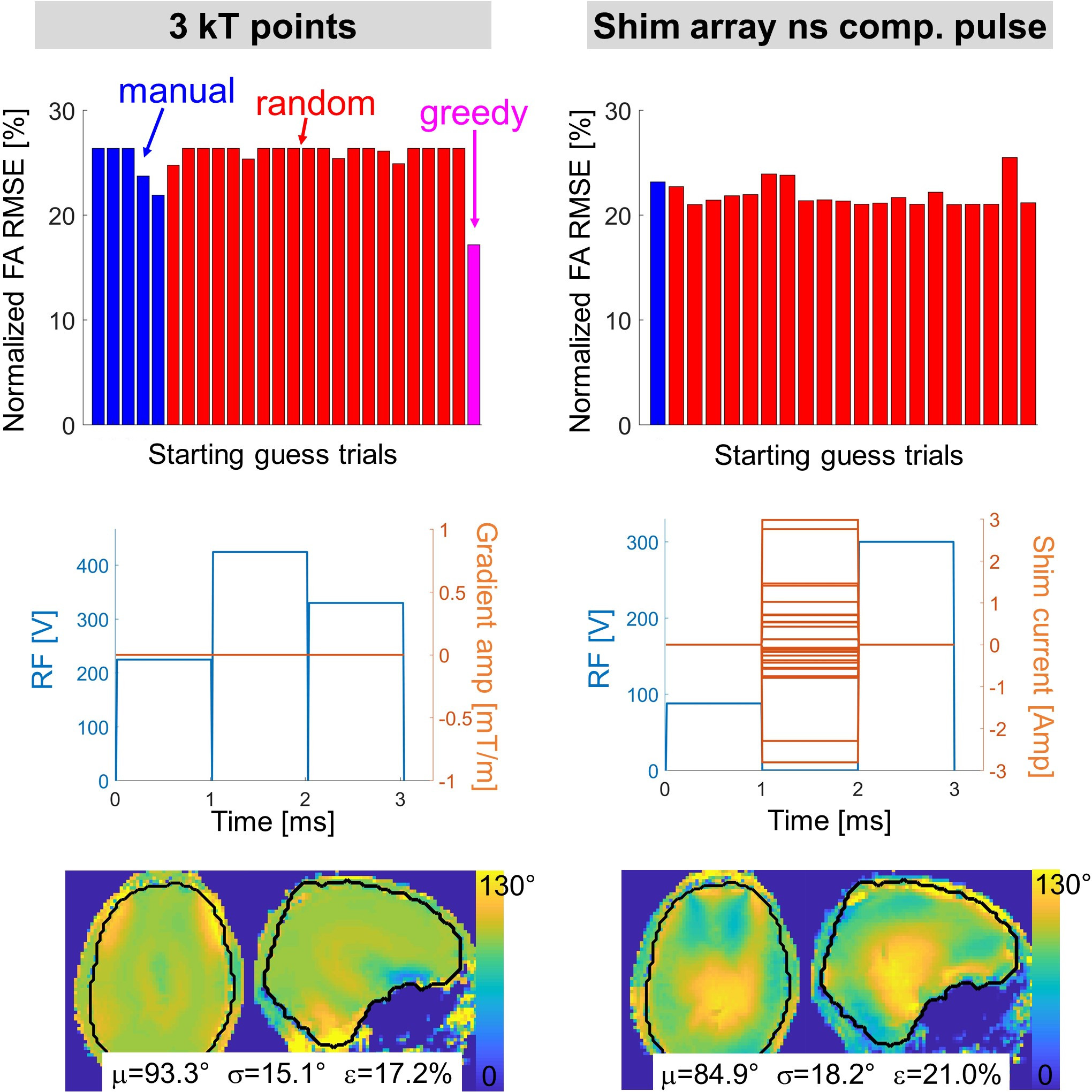
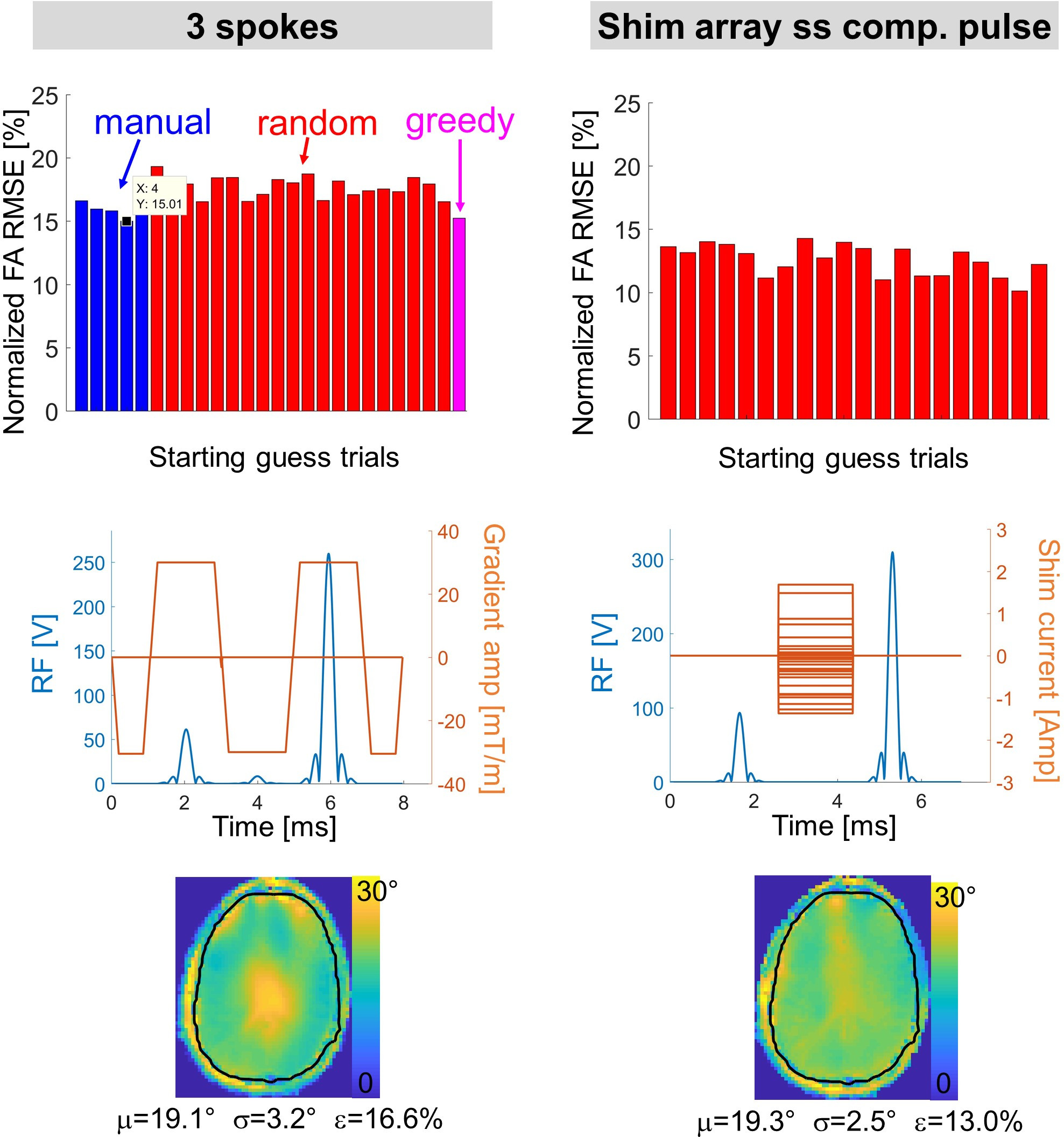
Numerical evaluation: We used B1+ and B0 field maps acquired in a human subject at 7T in all the numerical evaluations. We designed 90 degrees non-selective (RF-SA-RF), 180 degrees non-selective (RF-SA-RF-SA-RF) as well as 20 degrees slice-selective (RF-SA-RF) pulses using the RF/shim array method. We also designed standard kT-points [4] and spoke pulses [5] for comparison. kT-point and spokes were optimized using a greedy approach whereby sub-pulses were added one at a time, using the previous estimate of the pulse as the initial guess for the placement of the next sub-pulse.
Phantom measurements: We performed RF-SA-RF experiments in a head phantom at 7T. The birdcage’ B1+ map was measured using the product saturated-TFL sequence [6] (TR=10 seconds, TE=2ms, resolution=3mmx3mmx5mm). The B0 map was measured using the product GRE field-mapping sequence (same resolution). Maps were interpolated in a common reference frame along with the shim array element field maps. We inserted the SA composite pulses in a FLASH sequence and assessed the improvement in contrast weighting uniformity on PD-weighted images (flip-angle 20 or 90 degrees, TR=100ms, TE=10ms). The SA was triggered by the sequence.
Results & discussion
Fig. 1 shows that the RF-SA-RF strategy seems to outperform the optimized 2-spoke excitation for this particular phantom and slice position (10 degrees slice-selective excitations), which can be seen both on the flip-angle maps and the PDw-FLASH images. Fig. 2 shows a comparison of the target phase method [1] and our joint RF/shim current optimization for a non-selective excitation (90 degrees). The joint optimization performs better, especially in regions with significant B0 inhomogeneities. The waveform solutions created by both approaches are quite different, indicating different mechanisms. Fig. 3 shows an RF-SA-RF-SA-RF pulse for non-selective inversion of the magnetization. Good homogenization is obtained, which is not possible using only two RF sub-pulses (RF-SA-RF). Figs. 4 & 5 show that the performance of the RF/shim array strategy is slightly inferior to that of the best kT-point pulse, although this requires carefully choosing the kT-point locations (greedy optimization). In contrast, the slice-selective RF/shim array strategy performed better than the duration-matched bipolar optimized 3-spoke pulse.Conclusion
The RF/B0 shim array flip-angle mitigation strategy proposed by Rudrapatna et al [1] seems to outperform traditional spoke pulses for slice-selection, but not kT-points when those are properly positioned. This is due to the fact that the degrees-of-freedoms of the shim array can be used to create complicated phase patterns in 2D, but less so in 3D (this is similar to the superior performance of slice-by-slice B0 shimming compared to global shimming). For magnetization inversion and, we hypothesize, refocusing, a 3-sub-pulse strategy is required (RF-SA-RF-SA-RF). Flip-angle mitigation using shim arrays is potentially simpler than parallel transmission as the safety of this technique is the same as that of the birdcage coil and the SA field maps need only be acquired once (same for all subjects).Acknowledgements
JPS: NIH NIBIB R00EB021349; BG: NIH NIBIB R00-EB019482References
[1] Umesh Rudrapatna, S., et al. (2016). "Dynamic multi‐coil tailored excitation for transmit B 1 correction at 7 Tesla." Magnetic Resonance in Medicine 76(1): 83-93.
[2] Stockmann, J. P., et al. (2016). "A 32‐channel combined RF and B0 shim array for 3T brain imaging." Magnetic Resonance in Medicine 75(1): 441-451.
[3] Pauly, J., et al. (1991). "Parameter relations for the Shinnar-Le Roux selective excitation pulse design algorithm [NMR imaging]." Medical Imaging, IEEE Transactions on 10(1): 53-65.
[4] Cloos, M., et al. (2011). "kT‐points: Short three‐dimensional tailored RF pulses for flip‐angle homogenization over an extended volume." Magnetic Resonance in Medicine 67(1): 72-80.
[5] Saekho, S., et al. (2006). "Fast kz three-dimensional tailored radiofrequency pulse for reduced B1 inhomogeneity." Magnetic Resonance in Medicine 55(4): 719-724.
[6] Fautz, H., et al. (2008). B1 mapping of coil arrays for parallel transmission. ISMRM.
Figures