0470
A method for controlling wireless hardware using the pulse sequence, applications in prospective motion correction.1Clinical Neuroscience, Karolinska Intitutet, Stockholm, Sweden, 2Neuroradiology, Karolinska University Hospital, Stockholm, Sweden, 3MR Applied Science Laboratory Europe, GE Healthcare, Stockholm, Sweden
Synopsis
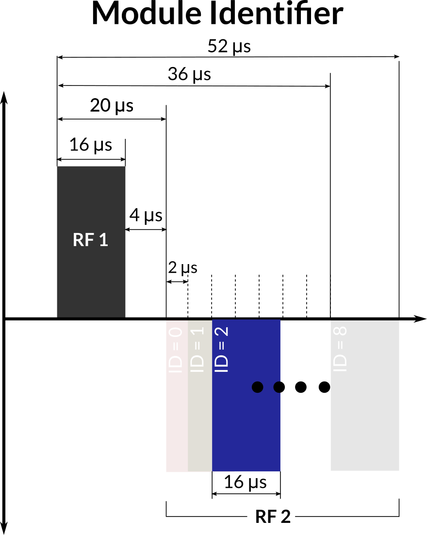
We explore a real-time method of controlling a wireless device using the pulse sequence - with a series of short RF pulses. We show that it is possible to encode and detect eight unique identifiers with a high reliability in 52 μs. Some identifiers are followed by short (< 1 ms) navigators that encode the pose of the device in the imaging volume. Other identifiers are followed by more RF pulses that encode information used for device configuration. These tools minimise the impact on the main pulse sequence and allow the device to tailor feedback precision to the pulse sequence requirements.
Introduction
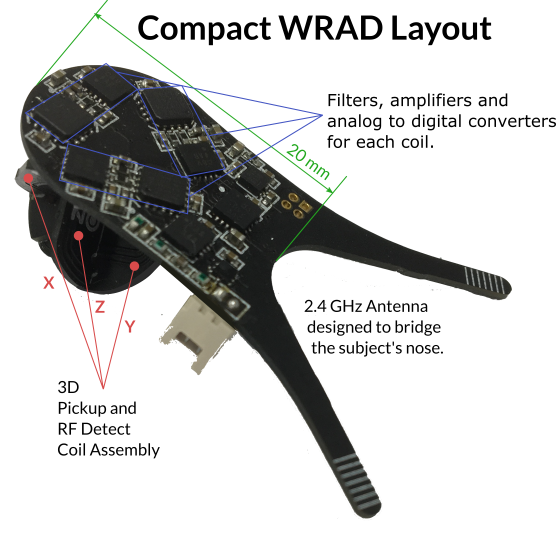
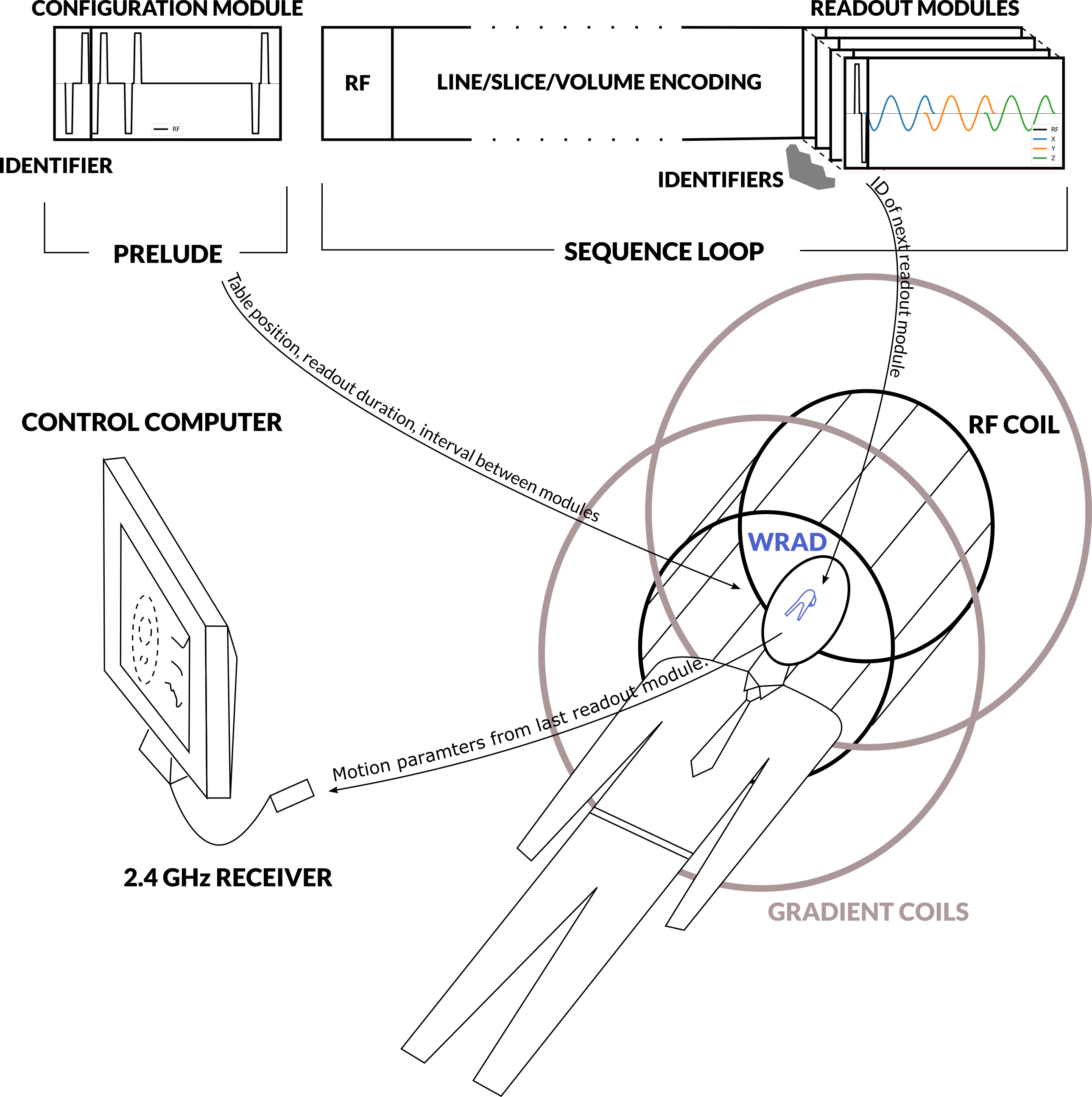
A wireless radio frequency triggered acquisition device WRAD (Figure 1) uses the rate of change of the gradient waveform and static magnetic field direction to determine the pose of the subject's head in the MRI scanner. The WRAD is battery powered and communicates its results via a low power 2.4 GHz radio link to allow easier fixation to the subject. To save energy and reduce the burden on the wireless link, the WRAD only acquires small portions of the pulse sequence, typically lasting less than one millisecond. This can be thought of as a short navigator. The WRAD needs to know precisely when this navigator is played out for correct interpretation of the gradient waveforms used to encode its location. In the previous implementations1-2, the WRAD detected RF pulses in the main pulse sequence and timed the relative offset to the start of its navigator, making it strongly dependent of the main sequence’s timing. Moreover, the WRAD was unable to distinguish between different RF pulse types. In this work, we greatly reduce the dependency on the main sequence by introducing a series of standalone readout modules that can be interleaved with the main sequence. Additionally, we wanted the WRAD to adapt to the current scan situation (e.g. the change in table position on a GE MRI system). To enable this, a second configuration sequence module was designed to send variables "over-the-air" from the sequence to the WRAD via short RF pulse trains.Methods
Hardware: A 3D RF detection circuit was designed and fabricated (Figure 1), minimising the effect of the orientation of the WRAD on detection sensitivity. The same coil set was used for sampling the gradient slew vector, reducing the overall size of the device.The readout and configuration pulse sequence modules were written using the KSFoundation3 EPIC abstraction layer. All the modules start with two 16 μs long bipolar (hard) RF pulses (Figure 2) with an amplitude that corresponds to a flip angle of 0.5° per pulse at 10 kHz off-resonance. The time between the rising edges of the pulses encodes the module’s identity.
Readout modules: Four IDs were reserved for readout modules. Based on the module ID the WRAD configures filter parameters for the readout, waits for the start of the gradient play-out and then samples the potential across the three pickup coils at 250 kHz. The readout modules were all forced to have the same duration, allowing them to be interchanged during the image acquisition (Sequence loop, Figure 3).
Configuration modules: use the remaining IDs, which are then followed by 6 more RF pulses that encode one byte per pulse (or three 16-bit variables per play-out). The module durations change based on the data encoded. In the current implementation, they are inserted before the main sequence begins (Prelude, Figure 3).
Experiment 1: Four different readout modules (Figure 4, column 2) were inserted into a 2D gradient echo sequence according to the slice loop plan shown in Figure 4, column 1. One module identified the “DUMMY” shots (row 3) allowing the WRAD to increase filter gains2 to ensure pre-imaging convergence. A pattern of two flipped polarity modules (“POS” - row1, “NEG” - row2) were played during the image acquisition, testing if the WRAD could possibly combine data from sequential readouts. The final module signifies the end of the slice loop (“LAST” - row4), allowing the WRAD to go to sleep.
Experiment 2: A configuration module was inserted before the sequence start and played out 10,000 times. This experiment was run on a GE Optima 450w 1.5 T and a GE SIGNA Premier 3 T scanner to evaluate robustness to different trigger strengths.
Experiment 3: A configuration module was used to set the number of cycles of the sinusoidal blips to two. The “POS” and following “NEG” raw data were then compared (Figure 5).
Results
Experiment 1: The WRAD successfully tagged each raw data payload without any false triggers (Column 3, Figure 4).Experiment 2: The same WRAD device achieved a 100% success rate on both MRI scanners.
Experiment 3: The RMS standard deviation of position for experiment 1 was 0.208 mm (single sinusoid). Increasing the sinusoids to two cycles reduced this to 0.137 mm for the “POS” module. Combining the slightly longer readouts (Figure 5, “POS” - “NEG”) gives the highest precision of 0.077 mm.
Discussion
The WRAD consistently identifies the short sequence modules with in-bore timing accuracy. This combined with the pre-scan configurations enables the WRAD to dynamically adapt to the pulse sequence design. Modules can be shortened for fast 3D imaging or lengthened to gain better precision for less frequent single-shot acquisitions. Although just a basic example has been presented here, it is possible to envisage new uses for the WRAD, from simple sequence loop debugging to gaining a vectorial insight into eddy currents.Conclusion
This work represents a promising new approach for interfacing external sensors with the scanner with minimal additional hardware and no physical connections to the scanner infrastructure. The WRAD’s ability to adapt to the pulse sequence simplifies complex interactions. This enables a reliable, highly customisable implementation that we hope will improve the efficacy of motion correction using external hardware.Acknowledgements
The author was at the University of Cape Town (UCT) for the development of the hardware used in this abstract. We would like to thank Ernesta Meintjes, UCT and RC&I for their support during this time.References
1. A. van Niekerk, E. Meintjes and A. van der Kouwe, "A Wireless Radio Frequency Triggered Acquisition Device (WRAD) for Self-Synchronised Measurements of the Rate of Change of the MRI Gradient Vector Field for Motion Tracking," in IEEE Transactions on Medical Imaging, vol. 38, no. 7, pp. 1610-1621, July 2019. doi: 10.1109/TMI.2019.2891774
2. van Niekerk, A, van der Kouwe, A, Meintjes, E. "Toward 'plug and play' prospective motion correction for MRI by combining observations of the time varying gradient and static vector fields". Magn Reson Med. 2019; 82: 1214– 1228. doi: 10.1002/mrm.27790
3. ISMRM 2017 #3813: Stefan Skare, Enrico Avventi, Ola Norbeck and Henric Rydén. "An abstraction layer for simpler EPIC pulse programming on GE MR systems in a clinical environment" url: http://ksfoundationepic.org/
Figures