0124
Specific Absorption Rate (SAR) Comparison in the Conventional and Open MRI Systems Utilizing an Anatomical Human Computational Model
Kyoko Fujimoto1, Tayeb A Zaidi1, David Lampman2, Joshua W Guag1, Hideta Habara3, and Sunder S Rajan1
1Center for Devices and Radiological Health, US Food and Drug Administration, Silver Spring, MD, United States, 2Hitach Healthcare Americas, Twinsburg, OH, United States, 3Healthcare Business Unit, Hitachi, Ltd., Tokyo, Japan
1Center for Devices and Radiological Health, US Food and Drug Administration, Silver Spring, MD, United States, 2Hitach Healthcare Americas, Twinsburg, OH, United States, 3Healthcare Business Unit, Hitachi, Ltd., Tokyo, Japan
Synopsis
There is an increasing use of open-bore vertical Magnetic Resonance (MR) systems which consist of two planar radio-frequency (RF) coils. These planar coils generate different electric field distributions compared to that of the conventional cylindrical coils. A recent study showed that RF-induced heating of a neuromodulation device was much lower in the open-bore system. However, imaging landmarks other than the brain have not been evaluated. In this study, we examined the differences in RF exposure using computational modeling and compared specific absorption rate in an anatomical human model at a 1.2T open-bore system with a 1.5T conventional system.
Introduction
There are two common risks faced in the practice of non-contrast Magnetic Resonance Imaging (MRI): adverse events such as skin burns and radio-frequency (RF) induced thermal injury in patients with implantable medical devices. Both risks are due to high electric field (E-field) exposure in tissue that is produced by the body RF coil for a given B1+ field needed for imaging1.The most common body RF coil design used is a cylindrical birdcage resonator. There is an increasing use of an open-bore vertical system which consists of two planar coils. The E-field distribution generated by the open system is different from that of the conventional cylindrical coil. A recent study showed that RF-induced heating of a neuromodulation device was much lower in the open system2. However, imaging landmarks other than the brain have not been evaluated. In this study, we examined the differences in RF exposure using validated computational modeling and compared specific absorption rate (SAR) in an anatomical human model in a planar coil (49.6MHz) and a conventional birdcage coil (64MHz).
Methods
Measurements for modeling validationFifteen data points of E-field and magnetic field (H-field) were collected in the ASTM phantom using a hand-held measurement system with an E-field probe and a H-field probe (EASY4MRI, SPEAG, Switzerland) in a 1.5T high-pass birdcage body coil (MITS1.5, Zurich Med Tech, Switzerland) and a commercial open-bore 1.2T MRI system (OASIS, Hitachi, Ltd., Japan). The data was acquired with a 5×3 grid with 9.45cm and 9cm spacing in the coronal slice.
The probes were calibrated to a specific pulse sequence which was not available at both systems. To mitigate this, the difference factors were calculated based on measurements using TEM Transmission cell (Model 8802, Narda, USA) for both probes at 49.6MHz and 64MHz. The measurement results were scaled independently with the difference factors.
Modeling
The simulations were first performed with the ASTM phantom at 49.6MHz for the open coil (Fig.1(a)) and at 64MHz for the conventional birdcage coil (Fig.1(b)) using the Sim4Life platform (V4.4, Zurich Med Tech, Switzerland). The ASTM simulation results were scaled with B1+ = 2μT at the coil isocenter. Then simulations with the AustinMan model3 were performed at the heart, hip bone, and knee imaging landmarks for both coils. The coils were modeled based on the physical coils used for the measurements (OASIS2,4 and MITS1.55). For the open simulation, the Huygens’ Approach6 was used. The incident field was calculated with an unloaded coil first, then used to compute fields within the body model with 2mm isotropic grid. For the birdcage simulation, the AustinMan model was discretized with 2mm and the coil was discretized up to 0.98mm to include small components in the grid. The birdcage results were resampled to 2mm isotropic grid. These grid differences are expected to have a minor effect to our results as a previous study reported7. The SAR1g results were normalized to whole-body SAR = 2W/kg.
Results
MeasurementThe scaled measurement results were compared with the simulation results (Fig.2). The correlation (R2) of the E-fields was 0.89 for the open coil and 0.99 for the birdcage coil. The correlation of the H-fields was 0.85 for the open coil and 0.71 for the birdcage coil.
Modeling
SAR1g results calculated in the AustinMan model were compared for each imaging landmark. The maximum SAR1g comparison showed that SAR1g in the birdcage coil was higher than that in the open coil for all the imaging landmarks (Fig.3(a)). The anatomical structures where the maximum SAR1g were found were different for each coil as summarized in Fig.3(b). The anatomical locations with the maximum SAR1g were identified in coronal slices (Fig.4). The SAR1g results were further analyzed and maximum values were calculated along the axial plane of the AustinMan body (Fig.5). The maximum SAR1g anatomical locations for heart, hipbone and knee were upper back, lower back and groin (for the open coil), and arm, groin and knee (for the birdcage coil), respectively.
Discussion
SAR1g maps showed considerably different distributions between the two coils. This was due to the differences in coil geometries as well as the locations of sources. For the birdcage coil, side of the bodies (arm and knee) showed higher SAR. For the open coil, body parts close to the bottom coil (upper and lower backs) showed higher SAR. These results suggest that for patients with implantable devices, a higher safety margin could be achieved if the scanner was chosen based on the advantageous E-field/SAR distributions for each coil type. For instance, there may be a lower risk of RF-induced heating in the open system for patients with knee implants as shown in Fig.5. Current MR Conditional implantable devices are limited to scanning on cylindrical systems. This study suggests that scanning on open coil systems may offer improved RF safety margins for some devices and expand patient access to MRI.Conclusion
The SAR1g results at the 1.2T open-bore system and the 1.5T conventional system showed that RF exposure is different at heart, hipbone and knee imaging landmarks. MR safety testing for implants designed to include MR systems with different coil architectures could provide improved patient access to MRI scans.Acknowledgements
Disclaimer: The mention of commercial products, their sources, or their use in connection with material reported herein is not to be construed as either an actual or implied endorsement of such products by the Department of Health and Human Services.References
- Song T, Xu Z, Iacono MI, et al. Retrospective analysis of RF heating measurements of passive medical implants. Magn. Reson. Med. 2018;80(6):2726-2730.
- Golestanirad L, Kazemivalipour E, Lampman D, et al. RF heating of deep brain stimulation implants in open-bore vertical MRI systems: A simulation study with realistic device configurations. Magn. Reson. Med. 2019;00:1-9.
- Massey JW and Yilmaz AE. AustinMan and AustinWoman: High-Fidelity, anatomical voxel models developed from the VHP color images. Conf Proc IEEE Eng Med Biol Soc 2016: 3346-3349.
- Suzuki S, Shimoda T, and Taniguchi T. High frequency coil for magnetic resonance imaging devices and magnetic resonance imaging using the same. JP2009022562. Japan Patent Office. February 5, 2009.
- Lucano E, Liberti M, Mendoza GG, et al. Assessing the electromagnetic fields generated by a radiofrequency mri body coil at 64 mhz: Defeaturing versus accuracy. IEEE Transactions on Biomedical Engineering, 2016;(63):1591–1601.
- Benkler, S., Chavannes, N., Kuster, N. Novel FDTD Huygens source enables highly complex simulation scenarios on ordinary PCs. Conf Proc IEEE APSURSI, 2009: 1-4.
- Fujimoto K, Angelone LM, Lucano E, et al. Effect of Simulation Settings on Local Specific Absorption Rate (SAR) in Different Anatomical Structures. Proc. ISMRM. Workshop on Ensuring RF Safety in MRI: Current Practices & Future Directions, 2017.
Figures
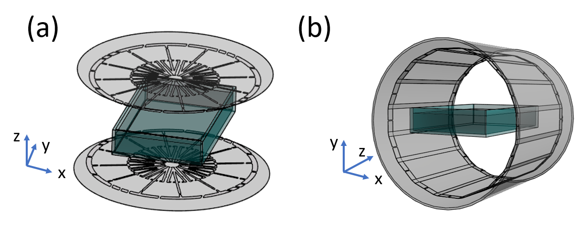
Figure 1: The modeling setup of the open and birdcage
coils with the ASTM phantom is shown.
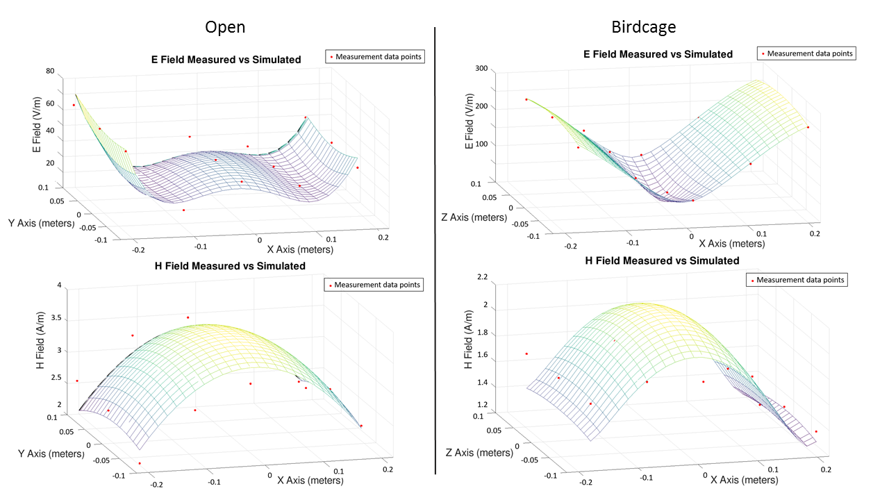
Figure 2: Comparisons
of measurements (red dots) and computational modeling data (surface meshes) at the
open and birdcage coils are shown. The correlation values were R2=0.86
and 0.85 for the E- and H- fields of the open system and R2=0.99 and
0.71 for the E- and H- fields of the birdcage system. The measurements were
taken in a plane at a height of -2.5 cm for
the open system, and 0 cm for the birdcage system relative to the coil isocenter.
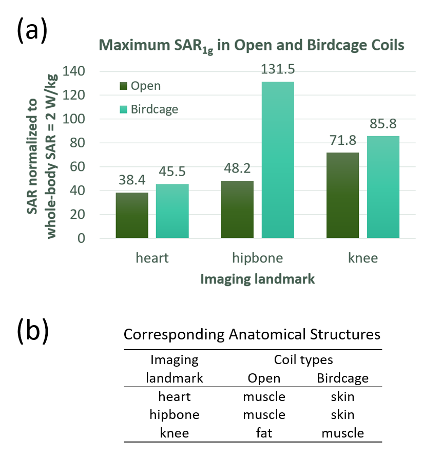
Figure 3: (a)
Maximum SAR1g in the open and birdcage coils are shown. (b) The
anatomical structures that maximum SAR1g values were found are
summarized.
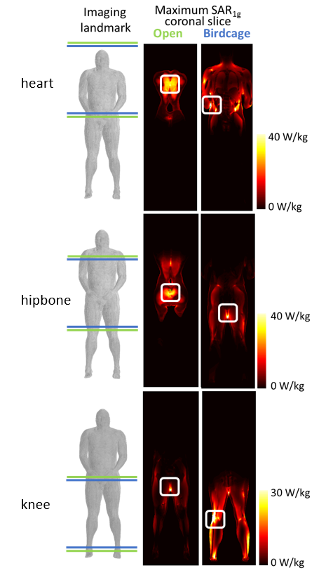
Figure 4: The
locations of the maximum SAR1g are shown in each landmark for both
coils with square boxes. The green lines in imaging landmark show the body area
covered by the open coil shield (935 mm in diameter); the blue lines show the
coverage by the birdcage shield (875 mm in length).
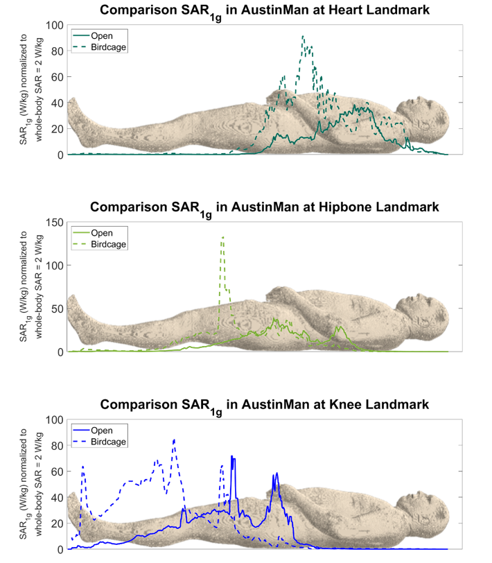
Figure 5: SAR1g
results were projected into axial direction and the maximum values are shown
along the AustinMan body for each coil and landmark.