0116
On the benefit of pTx for implant safety - a multiparameter simulation study
Johannes Petzold1, Sebastian Schmitter1, Bernd Ittermann1, and Frank Seifert1
1Physikalisch-Technische Bundesanstalt (PTB), Braunschweig and Berlin, Germany
1Physikalisch-Technische Bundesanstalt (PTB), Braunschweig and Berlin, Germany
Synopsis
FDTD simulations were used to generate the electromagnetic fields of a human voxel model with a generic implant in a pTx coil. B1+ homogeneity and SAR at the implant tip were systematically investigated for 4 field strength, 4 pTx channel counts, 3 implant positions and 6 excitation strategies. Simple and unsurprising conclusions can be drawn for 0.5 T (pTx is not necessary), 7 T (nothing goes without pTx), and on the channel count (the higher, the better). For the clinically most relevant field strength 1.5 T and 3 T, a much more complex pattern emerges.
Purpose
Wire-like metallic implants (e.g. spinal cord stimulators) can heat up at their tips during an MRI exam due to RF-field focusing. Aim of this work is to systematically investigate the theoretical possibilities and limitations of pTx to simultaneously achieve good $$$B_1^+$$$ homogeneity in a plane through the implant tip and low $$$\text{SAR}$$$ near the implant tip,1,2 i.e. for two experimentally accessible quantities3. To this end a simulation study was performed with a generic implant in a human voxel model and the target quantities were determined for different $$$B_0$$$, channel counts, implant positions and optimization strategies.Methods
FDTD simulations ($$$2\,\text{mm}$$$ resolution) of a generic pTx birdcage body coil in combination with an elongated L-shaped implant ($$$300\,\text{mm}\times20\,\text{mm}$$$, isolated except for $$$10\,\text{mm}$$$ at tip) inserted in the human voxel model "Duke"4 in 3 different positions (Fig. 1) were performed using Sim4Life (ZMT Zurich MedTech, Zürich, Switzerland). $$$E$$$-, $$$H$$$- and $$$J$$$-fields of the 48-port (16 ports on each end ring, 16 ports in the middle of the rungs) body coil were computed for $$$B_0=0.5\,\text{T,}\,1.5\,\text{T,}\,3\,\text{T}$$$ and $$$7\,\text{T}$$$. The field distributions of hypothetical coils with 4-channel and 8-channel coils were derived using electromagnetic co-simulation5. A 1-channel and 2-channel (degenerate) birdcage configuration was obtained by according superposition of the 8-channel fields.All following occurrences of $$$\text{SAR}$$$ refer to peak spatial $$$10\,\text{g}$$$ averaged $$$\text{SAR}$$$ ($$$\text{psSAR}_{10\,\text{g}}$$$). For simplicity, the average was carried out over the nearest $$$10\,\text{cm}^3$$$ in a sphere. The maximum $$$\text{SAR}$$$ in a $$$10\times10\times10$$$ voxel cube centered on the implant tip is denoted as $$$\text{tip}\,\text{SAR}$$$.
The following $$$B_1$$$-shimming (1-4) and 2-spokes (5,6) excitation modes were investigated:
- circular-polarized (CP) mode
- worst-case mode6: eigenvector to the largest eigenvalue of the matrix $$$\mathbf{Q}$$$ with $$$\text{tip}\,\text{SAR}=\langle\mathbf{v}|\mathbf{Q}|\mathbf{v}\rangle$$$ for excitation vector $$$\mathbf{v}$$$. This mode mostly serves as a reference to construct the
- orthogonal-projection mode7: projection of the CP excitation vector onto the subspace orthogonal to the worst-case excitation vector
- best-compromise mode2: direct minimization of the cost function $$\quad\,C=\frac{\text{tip}\,\text{SAR}}{k(\text{mean}\,B_1^+)^2}+\lambda\,\text{CV}(B_1^+)\qquad\text{for}\,k=10^{12}\text{W}/(\text{kg}\,\text{T}^2),\quad\lambda\in\{0,\,100,\,1000,\,\infty\}\quad(1)$$ with $$$\text{CV}(B_1^+)$$$ as coefficient of variation of $$$B_1^+$$$ in the transversal plane containing the implant tip by using the Nelder-Mead algorithm. As starting excitation vectors, the CP- and 99 different random starting excitation modes were used.
- 2-spokes (power regularization): Excitation vectors were obtained for a grid of predefined spokes positions, which were placed symmetrically around the origin with varying distance between the spokes (from $$$2-20\,\text{rad}/\text{m}$$$ in $$$1\,\text{rad}/\text{m}$$$ steps) and varying angle with respect to the x-axis (from 0°-180° in 5° steps). The cost function8 $$\quad\big\|\mathbf{|Av|-|m|}\big\|^2+\lambda\mathbf{v}^2\quad(2)$$ consisting of effective $$$B_1^+$$$ homogeneity $$$\big\|\mathbf{|Av|-|m|}\big\|^2$$$ and total input power $$$\mathbf{v}^2$$$ was minimized using Tikhonov optimization9 for 10 different starting excitation vectors. The first one was a CP excitation in both spokes, the remaining 9x2 spokes were choosen randomly.
- 2-spokes (best compromise): direct optimization of cost function$$$\:C\:$$$(Eq. (1)) for the same $$$k$$$-space positions and starting excitation vectors
Results/Discussion
A comprehensive summary of the target parameters $$$\text{CV}(B_1^+)$$$ and $$$\text{tip}\,\text{SAR}$$$ for implant position P1 but all field strengths and channel counts $$$n$$$ is shown in Fig. 3 as data points (modes 1-3) or L-curves (modes 4-6). The following observations are valid for all positions P1-P3.- Within the parametric modes (4-6), the hierarchy $$$4\triangleright5\triangleright6$$$ mostly holds, where $$$\triangleright$$$ points to "better", i.e. the L-curve is shifted towards the origin. Modes 4-6 always outperform the CP mode.
- The parametric modes always benefit from higher channel counts.
- At $$$0.5\,\text{T}$$$, $$$\text{tip}\,\text{SAR}<2\,\text{W}/\text{kg}$$$ for all tested cases. pTx improves $$$B_1^+$$$-homogeneity, but is irrelevant for safety.
- At $$$7\,\text{T}$$$, $$$\text{CV}\,B_1^+<0.6$$$ is only achievable with pTx.
- Again, $$$\text{CV}(B_1^+)$$$, $$$\text{tip}\,\text{SAR}$$$ and tip cost function gain from higher channel counts.
- The CP mode's $$$\text{tip}\,\text{SAR}$$$ equals the $$$\text{psSAR}$$$ for $$$0.5\,\text{T}$$$ (not shown), $$$1.5\,\text{T}$$$ and $$$3\,\text{T}$$$. However, this is not the case for $$$7\,\text{T}$$$ (not shown). The pronounced $$$\text{tip}\,\text{SAR}$$$ maximum at $$$3\,\text{T}$$$ hints at a wavelength dependent resonance. Implant length, which was not varied in the present work, might thus be another important parameter.
- With few exceptions, the same parameters behave better at $$$1.5\,\text{T}$$$ vs. $$$3\,\text{T}$$$. This conclusion may depend on the implant length.
- Less expectedly, $$$\text{psSAR}$$$, i.e. the global maximum, which was not part of the optimization strategies, exceeds $$$\text{tip}\,\text{SAR}$$$ in a variety of cases. The effect is not restricted to, but most dramatic at $$$3\,\text{T}$$$.
Conclusion
In the presence of metallic implants, both $$$B_1^+$$$ homogeneity and $$$\text{tip}\,\text{SAR}$$$ can benefit substantially from pTx also at clinical field strengths$$$\:3\,\text{T}$$$ and$$$\:1.5\,\text{T}$$$ (but not at$$$\:0.5\,\text{T}$$$). A pTx "mitigation" strategy focused on implant $$$\text{tip}\,\text{SAR}$$$ alone, however, can completely backfire and produce intolerable $$$\text{psSAR}$$$ values elsewhere in the body. This effect tends to become worse with higher $$$B_0$$$ and even a higher pTx channel count is not automatically beneficial, then. Implant length may be another important parameter and should be included in future studies.Acknowledgements
This work was funded by the EMPIR grant 17IND01 MIMAS. The EMPIR initiative is co-funded by the European Union’s Horizon 2020 research and innovation programme and the EMPIR Participating States.References
- Eryaman Y, Guerin B, Akgun C, et al. Parallel transmit pulse design for patients with deep brain stimulation implants. Magnetic Resonance in Medicine. 2015;73(5):1896-1903. doi:10.1002/mrm.2532
- McElcheran CE, Yang B, Anderson KJT, Golenstani-Rad L, Graham SJ. Investigation of Parallel Radiofrequency Transmission for the Reduction of Heating in Long Conductive Leads in 3 Tesla Magnetic Resonance Imaging. Xu B, ed. PLoS ONE. 2015;10(8):e0134379.
- Silemek B, Winter L, Seifert F, Pfeiffer H, Ittermann B. Measurement based mitigation of RF related safety hazards of implants in parallel transmission using temperature matrix. In: Proc. Intl. Soc. Mag. Reson. Med. Workshop on MR Safety. 2019:23. doi:10.1371/journal.pone.0134379
- Gosselin M-C, Neufeld E, Moser H, et al. Development of a new generation of high-resolution anatomical models for medical device evaluation: the Virtual Population 3.0. Phys Med Biol. 2014;59(18):5287-5303. doi:10.1088/0031-9155/59/18/528
- Kozlov M, Turner R. Fast MRI coil analysis based on 3-D electromagnetic and RF circuit co-simulation. Journal of Magnetic Resonance. 2009;200(1):147-152. doi:10.1016/j.jmr.2009.06.00
- Bardati F, Borrani A, Gerardino A, Lovisolo GA. SAR optimization in a phased array radiofrequency hyperthermia system. IEEE Trans Biomed Eng. 1995;42(12):1201-1207. doi:10.1109/10.476127
- Seifert F, Weidemann G, Ittermann B. Q matrix approach to control implant heating by transmit array coils. In: Proc. Intl. Soc. Mag. Reson. Med. 23. 2015:3212
- Setsompop K, Wald LL, Alagappan V, Gagoski BA, Adalsteinsson E. Magnitude least squares optimization for parallel radio frequency excitation design demonstrated at 7 Tesla with eight channels. Magnetic Resonance in Medicine. 2008;59(4):908-915. doi:10.1002/mrm.2151
- Grissom W, Yip C, Zhang Z, Stenger VA, Fessler JA, Noll DC. Spatial domain method for the design of RF pulses in multicoil parallel excitation. Magn Reson Med. 2006;56(3):620-629. doi:10.1002/mrm.2097
Figures
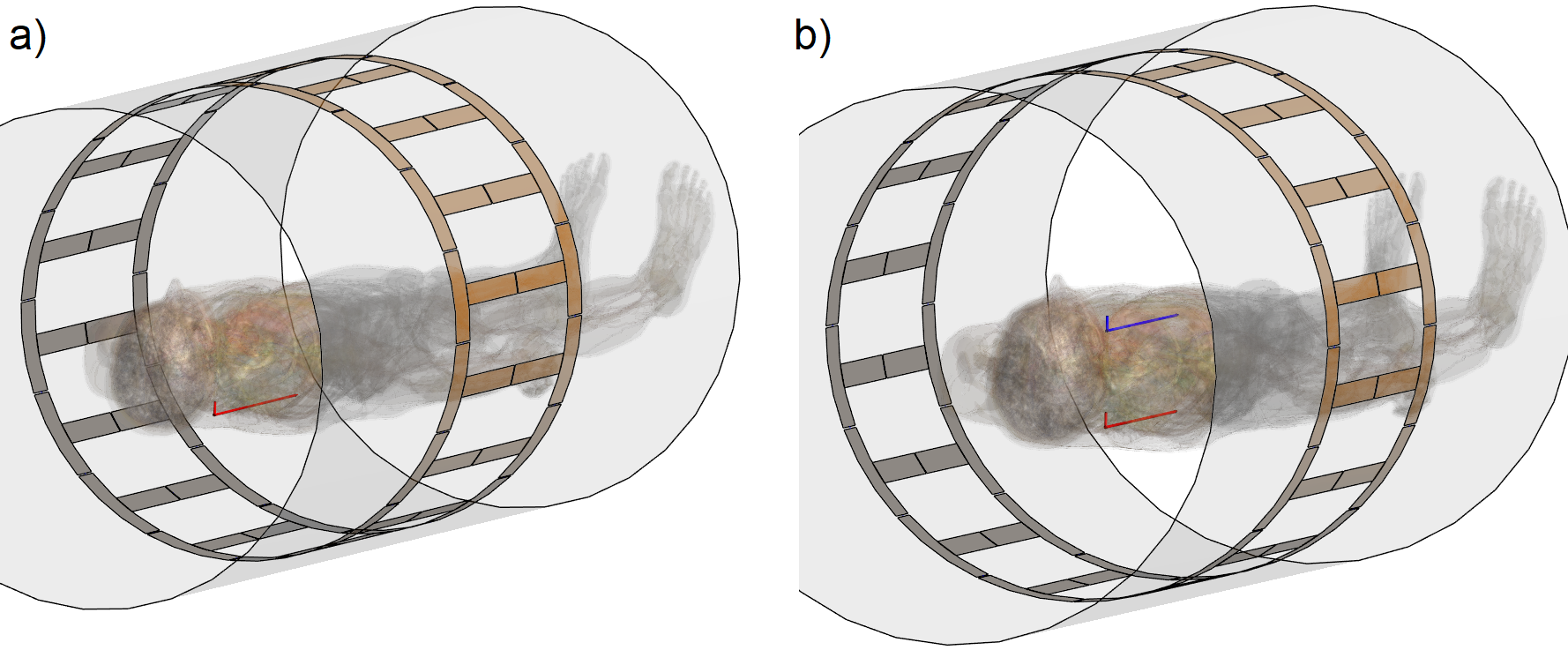
Fig 1. Simulation setups with pTx coil (orange), shield (gray) and implant (red/blue) in human voxel model "Duke"4. a) Duke, shifted by 30 cm in head-direction out of cardio imaging position with implant (red) in spinal cord stimulator position (Position P1). b) Duke in cardio imaging position. Position P2: red implant in spinal cord stimulator position. Position P3: blue implant on central axis of coil in thorax.
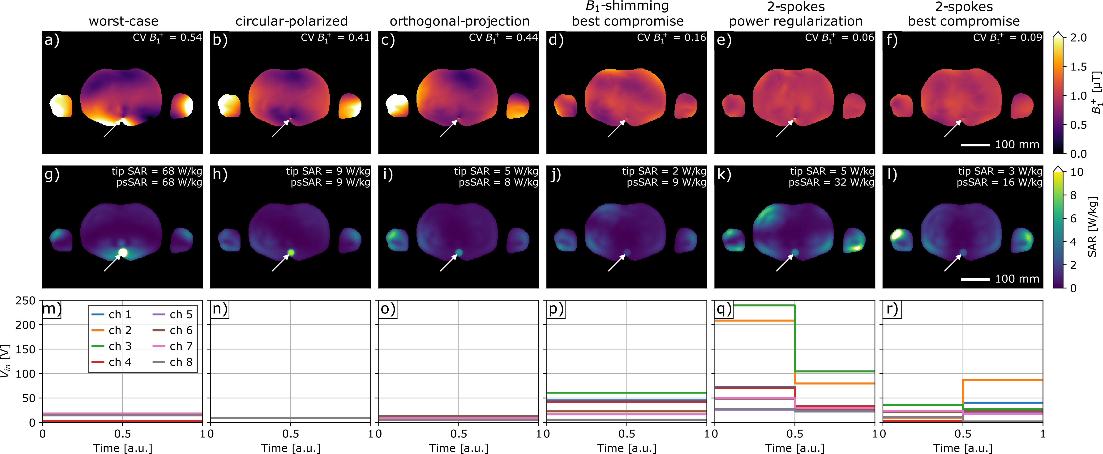
Fig 2. Comparison of B1-shimming (worst-case, circular-polarized, orthogonal-projection, best compromise) and 2-spokes (power regularization, best compromise) excitation modes in terms of B1+ (a-f), SAR (g-l) and incident voltage vector amplitudes (m-r) for lowest cost C = tip SAR/[k mean(B1+)^2]+100*CV(B1+) for k=1e12 W/(kg*T^2). The implant tip position P1 (Fig. 1a) is marked by an arrow, 8 channels at 3 T.
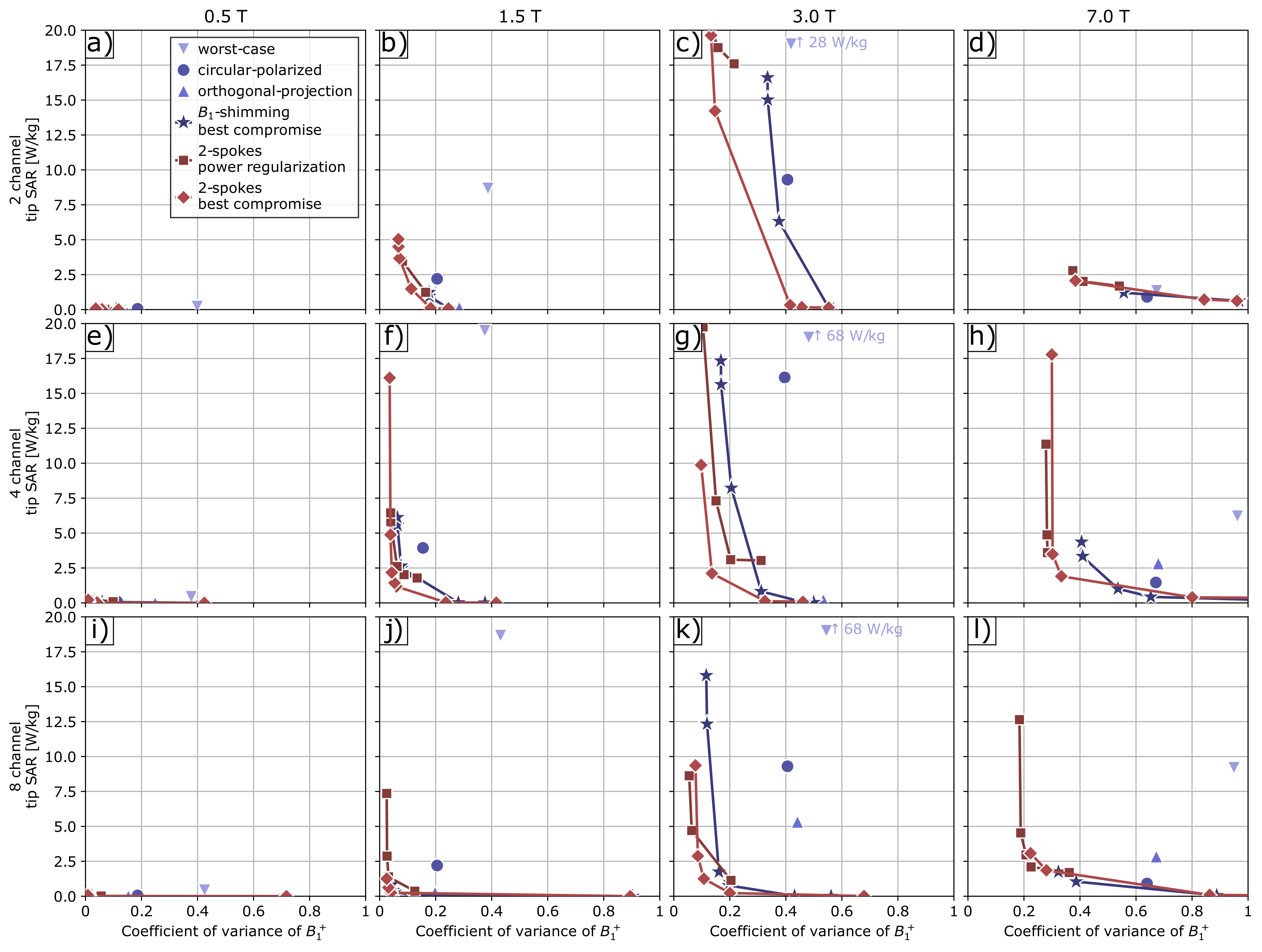
Fig 3. L-curves of tip SAR and coefficient of variance of B1+ of tested B1-shimming (worst-case, circular-polarized, orthogonal-projection, best compromise) and 2-spokes (power regularization, best compromise) excitation modes for 8, 4 and 2 ch pTx and 0.5 T, 1.5 T, 3 T and 7 T B0 field strengths. Implant position P1, see Fig. 1a.
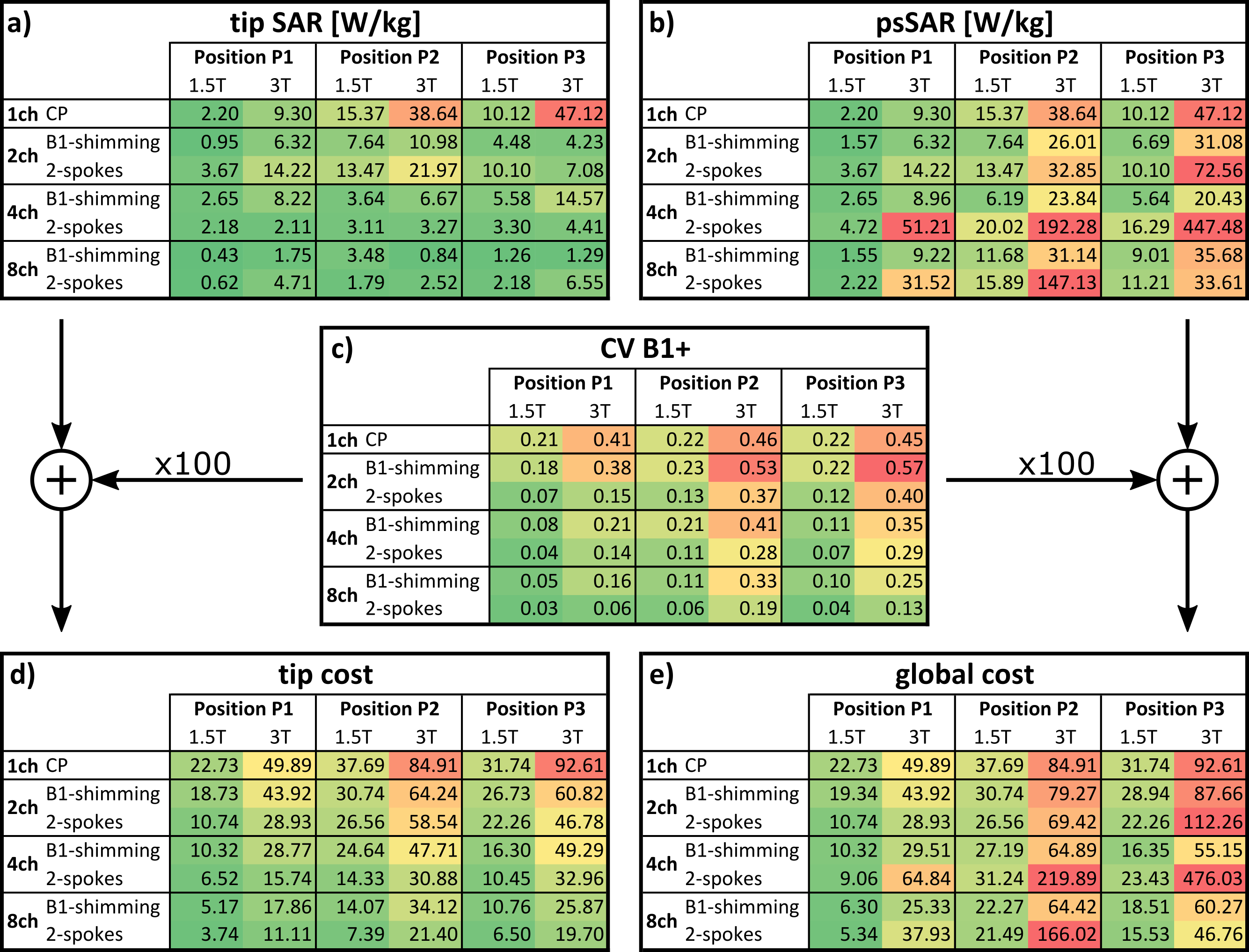
Tab. 1. Comparison of best compromise B1-shimming against best compromise 2-spokes in terms of tip SAR, psSAR, coefficient of variation of B1+ in the imaging plane and costs C = SAR+100*CV(B1+) for 1.5 T, 3 T and all tested implant positions (see Fig. 1); optimized for tip SAR cost.