0113
“Propeller Beanie” Passive Antennas to Alleviate Dark Bands in Transcranial MR-Guided Focused Ultrasound1Department of Radiology, Vanderbilt University Medical Center, Nashville, TN, United States, 2Institute of Imaging Science, Vanderbilt University, Nashville, TN, United States, 3Department of Biomedical Engineering, University of Virginia, Charlottesville, VA, United States, 4Department of Biomedical Engineering, Vanderbilt University, Nashville, TN, United States
Synopsis
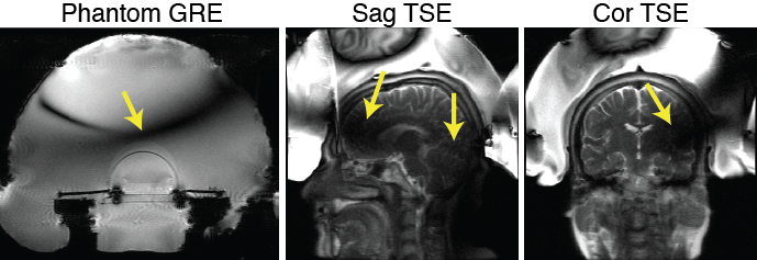
Transcranial MR-guided focused ultrasound (tcMRgFUS) neurosurgery is a non-invasive treatment for essential tremor and many emerging applications. In the FDA-approved Insightec tcMRgFUS system, however, RF reflections inside the transducer create a curved dark band in brain images that runs through midbrain locations that are targeted for essential tremor, and signal is reduced at least 25% everywhere in the brain, which limits the set of scans that can be performed during treatment. This work proposes a simpler solution that alleviates the problem, which is to place a passive reflecting antenna or resonator above the patient’s head, with a “propeller-beanie” crossed-wire shape.
Purpose
Transcranial MR-guided focused ultrasound (tcMRgFUS) neurosurgery is a non-invasive treatment for essential tremor and many emerging applications [1-3]. In the FDA-approved Insightec tcMRgFUS system, however, RF reflections inside the transducer create a curved dark band in brain images that runs through midbrain locations that are targeted for essential tremor, and signal is reduced at least 25% everywhere in the brain, which limits the set of scans that can be performed during treatment (Figure 1). To address this, researchers have proposed doping the water, and placing RF coils inside the water bath [4,5]. This work proposes a simpler solution that almost completely alleviates the problem, which is to place a passive reflecting antenna or resonator above the patient’s head, with a “propeller-beanie” crossed-wire shape.Theory
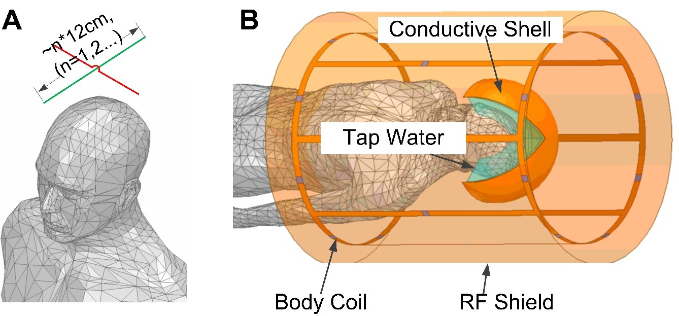
During tcMRgFUS treatment, the water bath couples acoustic energy into the head and cools the scalp. The water is a high permittivity dielectric with approximately 9x shorter RF wavelength than free space. At the same time, the transducer has a conductive inner surface that acts as an RF shield. Therefore, the electromagnetic waves that interact with the brain for imaging must travel from the bottom opening of the transducer to the top, where they are reflected. The reflected and incoming waves cancel approximately one quarter-wavelength from the top of the transducer (Figure 1). The proposed antennas alleviate the wave cancellation by reflecting the incoming RF waves back down into the head before they arrive at the transducer’s upper surface and reflect [6]. Unlike reflections from the transducer surface, the reflected waves’ amplitude and phase can be controlled by appropriate design of the antenna, by varying its wire lengths, layout/shape and position, so that the reflected waves add constructively with the incoming RF waves instead of canceling them. Figure 2a illustrates such an antenna placed above a human head model.Methods
Electromagnetic (EM) SimulationFigure 2b show a simulation model in the EM Solver Ansys HFSS. The body coil was modeled as a low-pass birdcage with diameter/length 60cm/100cm. The transducer bowl was modeled as a conductive surface on a 35 cm-diameter hemisphere. It was filled with tap water (conductivity=0.01 S/m, relative permittivity=81.) The head model was positioned at the center of the coil and immersed in the tap water. A pair of 26-gauge crossed tin-coated copper wires was placed ~1cm above the head. The wires’ lengths were 12cm, which equals the half-wavelength of the 3T Larmor frequency in the water. The simulations used the EM and RF circuit co-simulation method.
Experiment
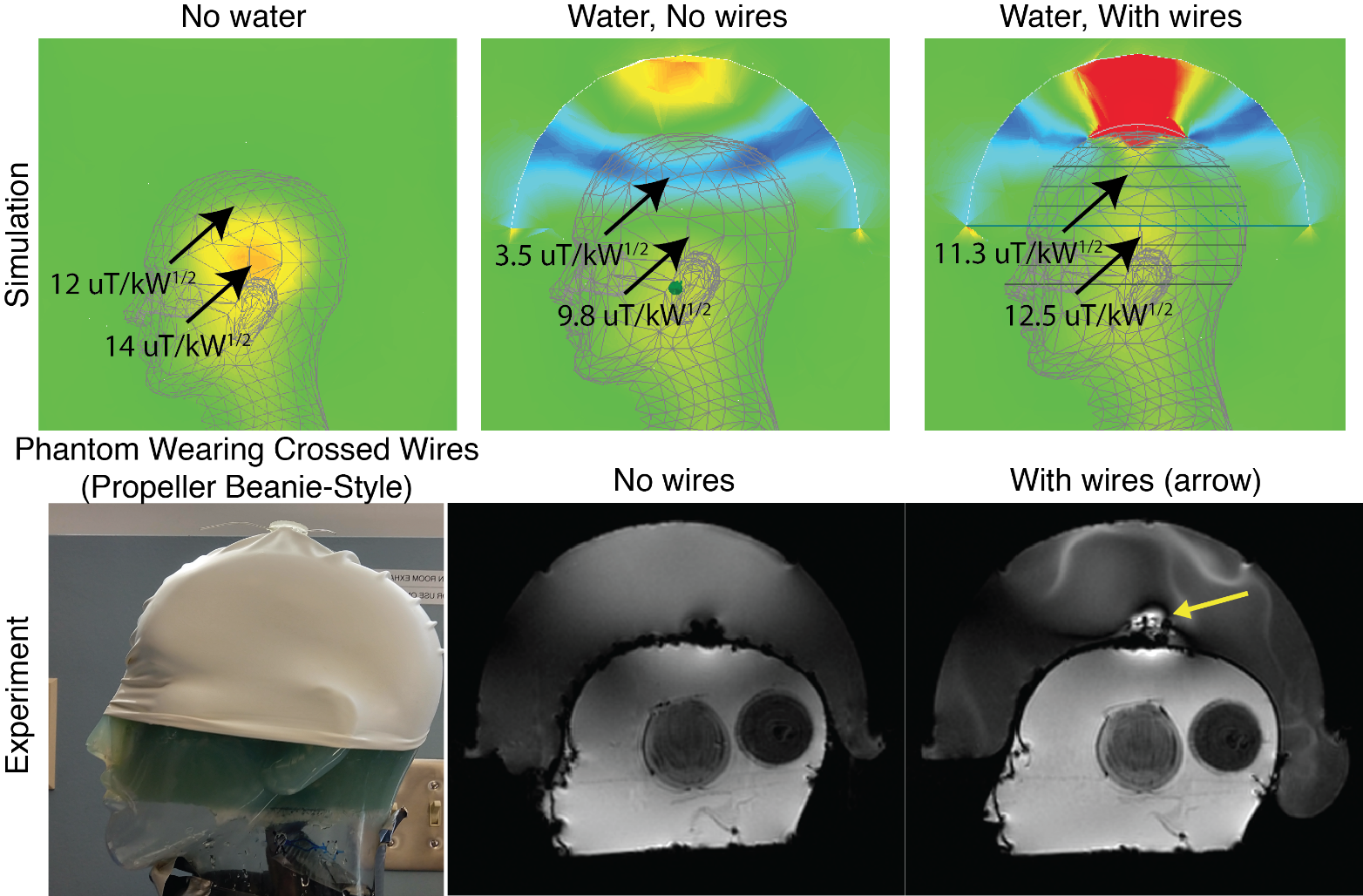
An imaging experiment was conducted to validate the signal improvements. A 3D-printed holder was made to attach to the top of a swim cap and hold a pair of 12 cm 26-gauge wires 1 cm above the head. The cap was placed on a head-shaped plastic mold containing 4% agar gel doped with approximately 2 mM CuSO4 as well as onions for contrast, which was then placed in the Insightec ExAblate Neuro 4000 system (Insightec Ltd, Tirat Carmel, IL) installed at a GE Discovery MR750T 3T scanner (GE Healthcare, Waukesha, WI). Sagittal gradient-recalled echo (GRE) images (TE 6 ms, TR 50 ms, 2 NEX, 40 cm FOV, 40 degrees flip (nominal), slice thickness 3 mm, 256 x 256 matrix, 62.5 kHz bandwidth) were acquired with and without the wires.
Results
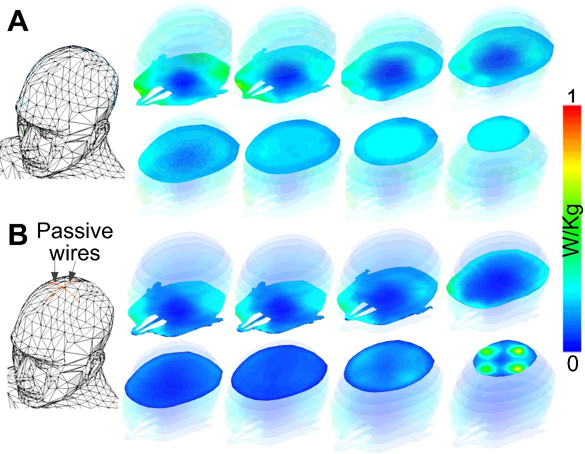
Figure 3 shows the simulation and experimental results. Without the water bath filled, the RF transmit (B1+) field in the brain contains characteristic center brightening. With water, a dark band appears where the B1+ is attenuated approximately 4x, and B1+ is attenuated at least 30% everywhere in the brain. The RF receive (B1-) field is similarly impacted (not shown), which compounds the signal loss in practice. The experimental images in the second row of Figure 3 show the phantom wearing the “propeller beanie” antenna, and two GRE images measured without and with the crossed wires present. The wires alleviated the dark band in the brain and shifted it up in the water bath. Note that these experimental images were further weighted by the nonuniform receive (B1-) field. Figure 4 shows the slice-by-slice 10-gram local Specific Absorption Rate (SAR) distributions without (Figure 4A) and with (Figure 4B) the passive wires. Even with the unoptimized antenna, the worst 10-gram SAR in the whole head only increases by 31%. This is because the passive wires increase the 10-local SAR nearby (i.e., at the top of the head) while the highest SAR without the wires appears in the middle of the head.Discussion and Conclusion
In this work, we explained how the dark band is generated in the Insightec tcMRgFUS system and proposed simple crossed-wire “propeller beanie” passive antennas to alleviate it. In practice, the wires can be high gauge to prevent interference with the FUS beam (which may be a problem for metal screen reflectors [7]), and they can be strung across the inside of the transducer or held in place by a holder that runs along the transducer seams, so that the patient need not wear a cap.Acknowledgements
This work was supported by NIH R01 EB 016695.References
1. Focused Ultrasound Foundation. Brain Program’s mini-workshop called “a landmark example” of academic–industrial collaboration. Aug 2012. https://www.fusfoundation.org/Newsletter-Articles/brain-programs-mini-workshop-called-a-landmark-example-of-academic-industrial-collaboration
2. McDannold, N., 2005. Quantitative MRI-based temperature mapping based on the proton resonant frequency shift: review of validation studies. International journal of hyperthermia, 21(6), pp.533-546..
3. McDannold, N., Clement, G.T., Black, P., Jolesz, F. and Hynynen, K., 2010. Transcranial magnetic resonance imaging–guided focused ultrasound surgery of brain tumors: initial findings in 3 patients. Neurosurgery, 66(2), pp.323-332.
4. Leung, S., Ghanouni, P. and Butts Pauly, K., 2015. Reduction of dielectric artifacts within an InSightec ExAblate 4000 head transducer. Journal of therapeutic ultrasound, 3(1), p.P27.
5. Watkins, R.D., Bitton, R. and Butts Pauly, K., 2014. Integration of an inductive driven axially split quadrature volume coil with MRgFUS system for treatment of human brain. In Proceedings 22nd Scientific Meeting, International Society for Magn Reson Med, Milan (p. 2330).
6. Yan, X., Gore, J.C. and Grissom, W.A., 2018. Traveling‐wave meets standing‐wave: A simulation study using pair‐of‐transverse‐dipole‐ring coils for adjustable longitudinal coverage in ultra‐high field MRI. Concepts in Magnetic Resonance Part B: Magnetic Resonance Engineering, 48(4), p.e21402.
7. Hadley, J.R., Odeen, H., Merrill, R., Haag-Roeger, R.C., Rieke, V., Payne, A., and Parker, D.L., 2019. Improving image quality in transcranial magnetic resonance guided focused ultrasound using a copper screen. In proceedings of the 19th ISTU, Barcelona.
Figures