0112
Mitigating Peripheral Nerve Stimulations for MRI Gradient Coils using Surface Electrodes1A.A. Martinos Center for Biomedical Imaging, Massachusetts General Hospital, Dept. of Radiology, Charlestown, MA, United States, 2Harvard Medical School, Boston, MA, United States, 3Computer Assisted Clinical Medicine, Medical Faculty Mannheim, Heidelberg University, Mannheim, Germany, 4Harvard-MIT Health Sciences and Technology, Cambridge, MA, United States
Synopsis
Peripheral Nerve Stimulation is becoming an important limitation for state-of-the-art head gradients, which despite higher PNS thresholds, are also operated at higher slew-rate and have limited degrees-of-freedom for FOV design mitigation strategies. We introduce a new mitigation approach, which uses contact surface electrodes driven simultaneously with the gradient coils to cancel the E-field induced by switching of the coil, thus increasing its PNS thresholds. We simulated the capability of four sets of electrodes placed in different areas of the face and found an up to 56% PNS reduction for the analyzed X-axis of a commercial head gradient coil.
Target audience
MR safety researchers, MRI gradient designers, MR engineersPurpose
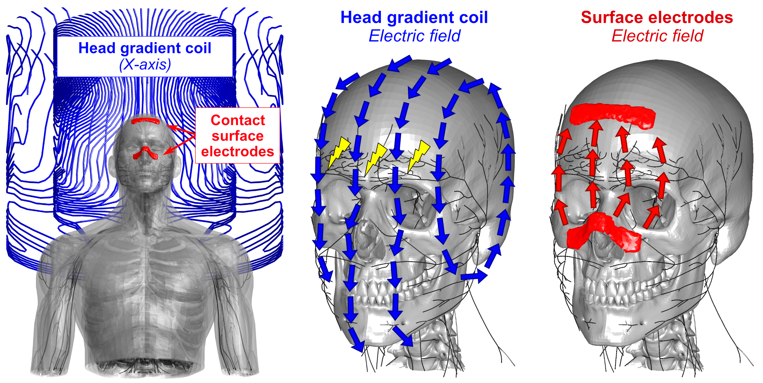
Peripheral Nerve Stimulation (PNS) is a significant limitation in fast MRI, including the latest generation of head gradient coils [1,2] that reach slew-rates up to 500 T/m/s. Since the E-fields are directly responsible for PNS, their reduction is a way to mitigate PNS. Strategies to reduce induced E-fields include reduced gradient FOV [3] (and thus dB/dt), and design approaches exploiting the degrees-of-freedom in the concomitant B-field terms [4,5] which can impact the E-fields without affecting gradient linearity. Although very promising for body gradients (where PNS occurs outside of the FOV), these approaches are less effective for head gradients where peak dB/dt occurs in the FOV. In this work, we propose and alternative approach which directly cancels the coil’s E-fields by creating an opposed E-field using surface electrodes driven simultaneously with the coil (Fig. 1). We use our recently developed PNS framework [6,7] and the linear PNS oracle formulation [8] to assess the mitigation efficiency and required voltages of different electrode configurations.Methods
We simulated the E-fields induced by a head gradient coil (X-axis of the Siemens AC84) as well as from four sets of surface electrodes in a male body model. All sets of electrodes shared the same ground electrode on the forehead, but used different locations for the cathodes (see Figs. 2 and 3): E1) on the nose, E2), above the jaw, E3) on the cheekbones, and E4) on the chin. The E-field induced by each configuration was simulated for a 1V cathode voltage (perfectly coupled to the body) using an ohmic electro-static solver (Sim4Life, Zurich MedTech) on an isotropic 1 mm3 hexahedral mesh. The E-field induced by the gradient coil was simulated for a slew-rate of 500 T/m/s using Sim4Life’s low-frequency quasi-static solver. For both sources (coil and electrode), we computed the electric potential changes along all nerves (by projection and integration of the E-fields along the nerves) and extracted the PNS oracle for the coil ($$$\text{PNSO}_{\text{coil}}$$$) and electrode ($$$\text{PNSO}_{\text{elec}}$$$) [8]. These vectors assign a PNS oracle value to every nerve segment that is inversely proportional to the PNS thresholds. Importantly, the PNS oracle metric is linear in the E-field (and thus in the coil currents/electrode voltages), which allowed us to quickly assess PNS when both sources are driving simultaneously. For each electrode set, we identified the optimal cathode voltage $$$\Delta V_{\text{opt}}$$$ such that the coil’s PNS oracle hot-spots are optimally counteracted, without inducing unwanted nerve activation elsewhere:$$\Delta V_{\text{opt}}= \text{arg min}_{\Delta V} \left\{ \text{max}\left\{ |\text{PNSO}_{\text{coil}} + \Delta V \cdot \text{PNSO}_{\text{elec}}| \right\} \right\} $$
Results
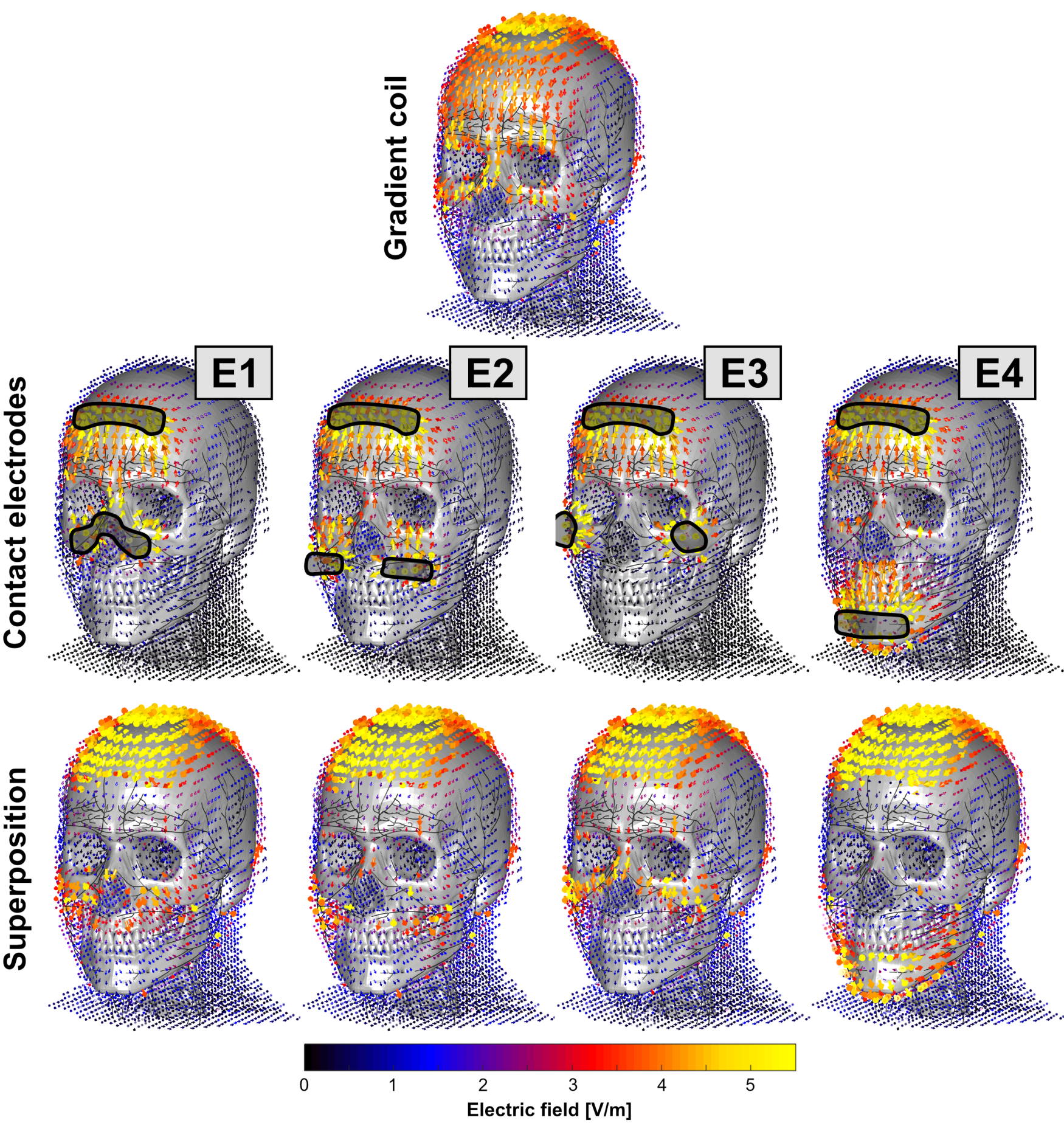
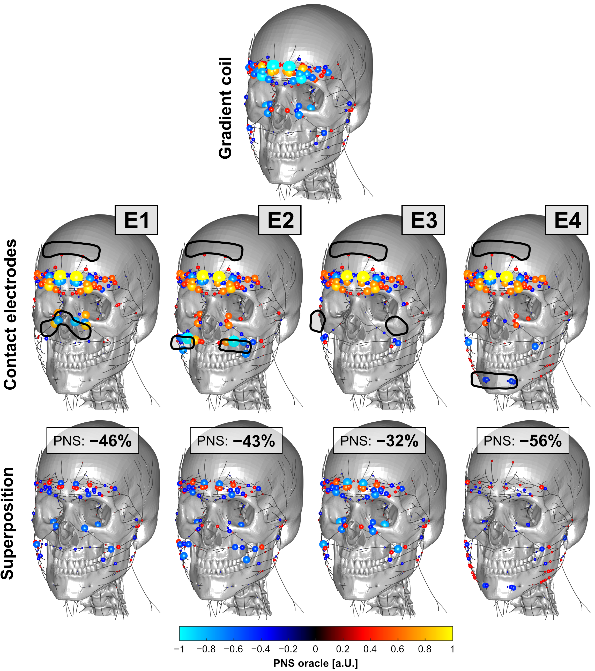
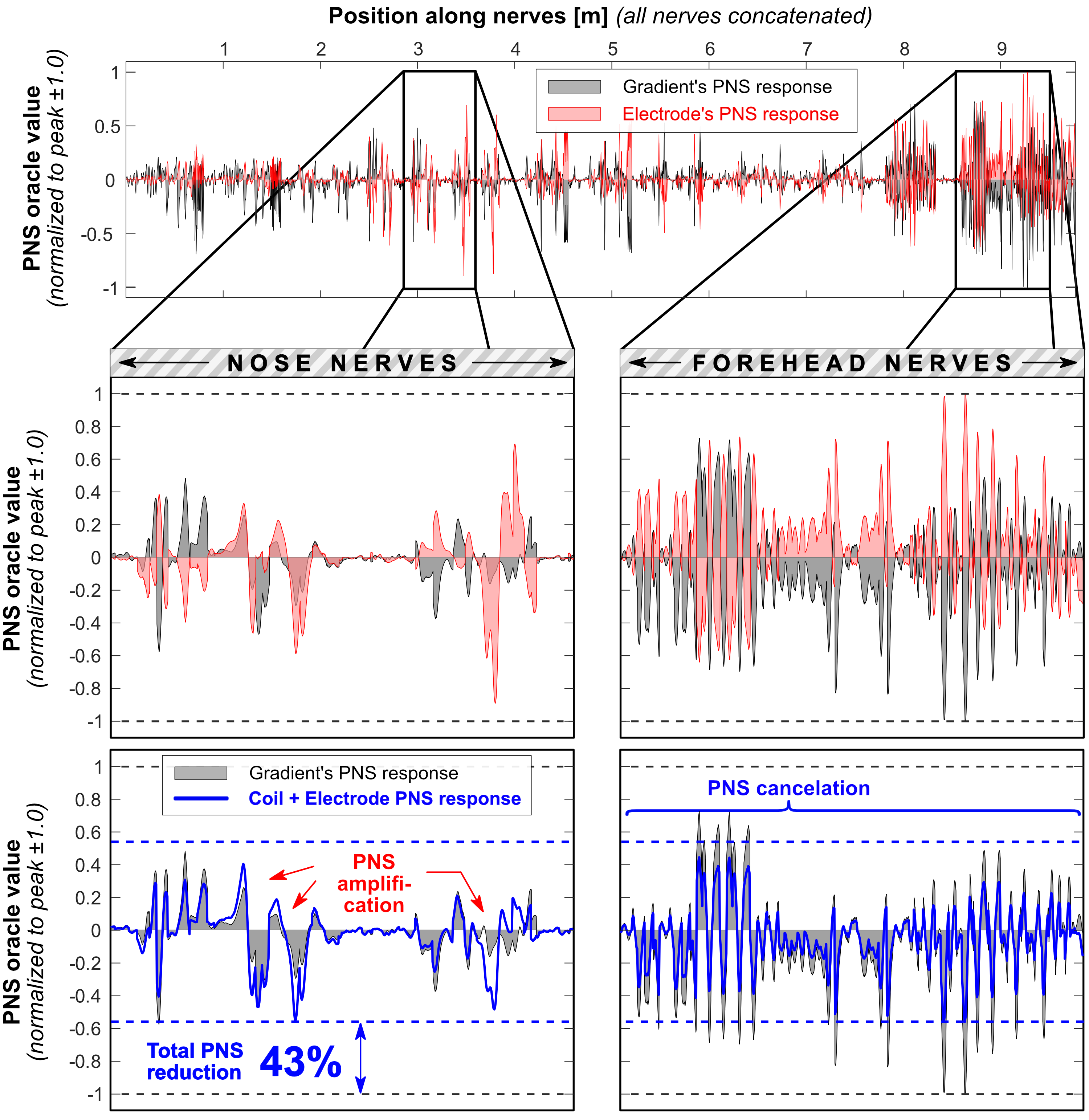
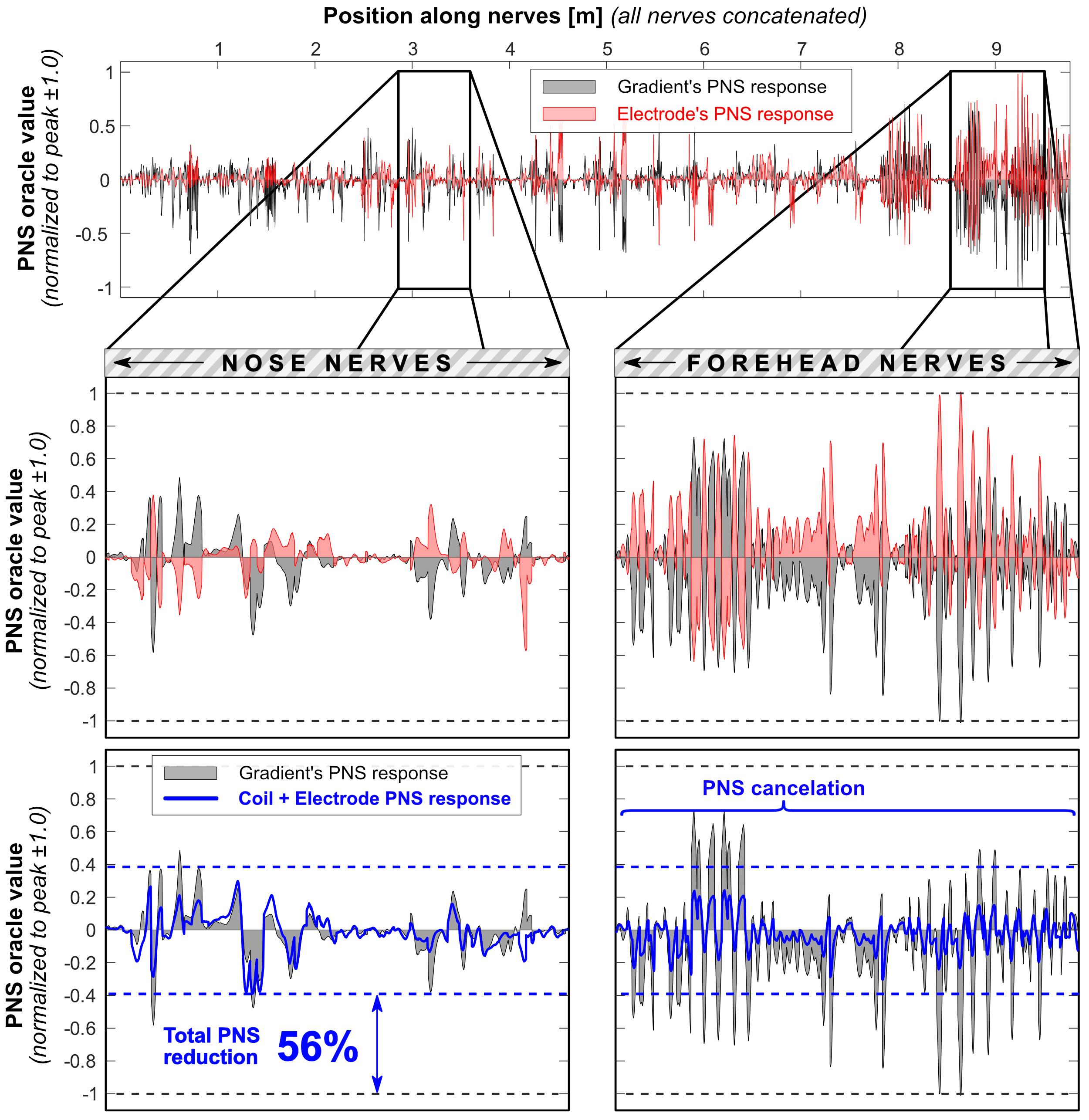
Figure 2 shows the E-fields for the coil, electrodes and superposition that optimally mitigates PNS. All electrode configurations cancel the E-field in the forehead reasonably well but lead to increased E-fields around the electrodes (especially on the scalp). Figure 3 shows PNS oracle maps corresponding to the E-field maps of Fig. 2. The coil’s E-field activates nerves in the forehead and nose area which can be counteracted with the opposite sign E-field and oracle (improving the PNS thresholds). The electrodes also interact with nearby nerves, i.e., in the nose area (E1 and E2), above the jaw (E2, E3, E4), and on the chin (E4). These secondary activations ultimately limit the achievable PNS reduction to between 32% (E3) and 56% (E4). Figures 4 and 5 show 1D plots of the PNS oracle values along all simulated nerves (all nerves concatenated) for E2 (Fig. 4) and E4 (Fig. 5), with zooms onto the nerves of the nose (left sub panels) and the forehead (right sub panels). Both electrodes create very similar PNS responses in the forehead (a pre-requisite for PNS reduction), however, E2 leads to an unwanted nerve activation in the nose/cheek, reducing its overall PNS mitigation capability (43% PNS reduction). Electrode set E4 improves the PNS mitigation by creating similar PNS responses in both the forehead and the nose/cheek, leading to a total PNS reduction of 56%. The required electrode voltages were a few 100 mV, although realistic applications most likely require higher voltages (due to imperfect coupling of the electrodes to the body).Discussion
We demonstrated how contact surface electrodes driven simultaneously with head gradient coils might allow for an up to 56% reduction in PNS. Importantly, for most body parts and gradient coils, there are only a few particularly sensitive nerves, suggesting that only a small number of electrodes might be needed to significantly reduce PNS. In this work, two or three electrodes were needed to target the most relevant nerves. The electrode’s PNS reduction relies on the fact that E-fields/currents are largely affected by the anatomy of the conductive tissue, yielding similar E-field patterns for different sources (coils and electrodes). For example, the anatomy of the face area forces electric currents through a “bottle-neck” at the bridge of the nose. Placing the electrodes at locations free of sensitive motor nerves can create a current flow through the same area with opposing sign to significantly reduce PNS. Greater PNS improvements may be possible by assessing other electrode configurations or by utilizing a larger number of electrodes and optimizing the relative voltage differences subject to optimal PNS mitigation.Acknowledgements
Research was supported by the NIBIB of the National Institutes of Health under award numbers R00EB019482, U01EB025121, and U01EB025162. The content is solely the responsibility of the authors and does not represent the official views of the National Institutes of Health.References
[1] Lee et al., “Peripheral nerve stimulation characteristics of an asymmetric head-only gradient coil compatible with a high-channel-count receiver array”, MRM 76(6), 2015
[2] Tan et al., “Peripheral nerve stimulation limits of a high amplitude and slew rate magnetic field gradient coil for neuroimaging”, MRM 83(1), 2019
[3] Zhang et al., “Peripheral nerve stimulation properties of head and body gradient coils of various sizes”, MRM 50(1), 2003
[4] Hidalgo-Tobon et al., “Reducing peripheral nerve stimulation due to gradient switching using an additional uniform field coil”, MRM 66(5), 2011
[5] Davids et al., “Peripheral Nerve Stimulation (PNS) constrained gradient coil design within a Boundary Element Method Stream Function (BEM-SF) optimization”, ISMRM 2019
[6] Davids et al., “Predicting Magnetostimulation Thresholds in the Peripheral Nervous System using Realistic Body Models”, Sci Rep 7(1), 2017
[7] Davids et al., “Prediction of peripheral nerve stimulation thresholds of MRI gradient coils using coupled electromagnetic and neurodynamic simulations”, MRM 81(1), 2019
[8] Davids et al., “Optimizing selective stimulation of peripheral nerves with arrays of coils or surface electrodes using a linear peripheral nerve stimulation metric”, J Neural Eng, 2019
Figures