0110
Dynamic control of RF currents in conductive guidewires with an auxiliary PTx system: First in vivo experience in sheep1Biomedical Engineering Department, School of Biomedical Engineering and Imaging Sciences, king's College London, London, United Kingdom, 2Siemens Healthcare Limited, London, United Kingdom, 3Centre de recherche Cardio-Thoracique de Bordeaux, Bordeaux, France, 4RAPID Biomedical GmbH, Rimpar, Germany
Synopsis
This paper presents first in vivo results of a parallel transmit (PTx) system adept at regulating radiofrequency induced guidewire heating, during MRI guided interventions in sheep. The PTx system, which is an add-on to an unmodified conventional 1.5T scanner, regulates heating by operating in modes that couple/decouple the guidewire from the radiofrequency transmit array. With an inserted guidewire decoupling modes allow operation with unrestricted B1+ to safely visualize anatomy, while the coupling mode operated at low radiofrequency power provides safe visualization of the guidewire itself. Temperature measurements at the guidewire tip and in vivo images are shown.
Introduction
Non-ferrous metallic devices, such as those used for cardiovascular interventions, pose a risk when used in MRI because they are susceptible to radiofrequency induced current, which can produce dangerous tissue burns.1Additionally, visualizing standard guidewires with MRI is difficult. However, substantial control of the radiofrequency (RF) current can be obtained by controlling the RF electric and magnetic (B1+) fields using parallel transmit (PTx) array coils.2 In a PTx system, it is possible to use a current sensor to determine maximum current modes (MC) in which the RF excitation yields a strong current on the conductor, and null current modes (NC) 2–4 in which zero current is measured at the sensor location, despite still generating B1+ fields. Here, we present first in vivo experiments to safely image anatomy and visualize a guidewire using an auxiliary active PTx (a-PTx) system that can be interfaced to a conventional scanner and perform a standard cardiac imaging workflow.Methods
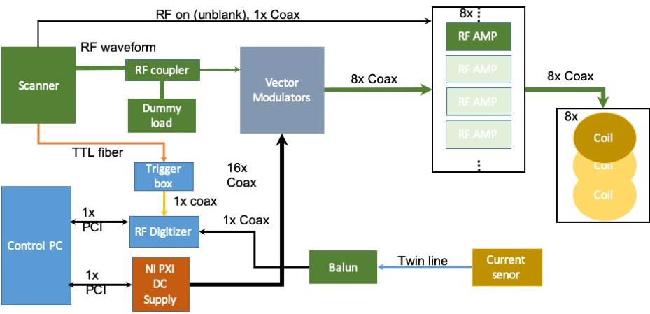
System architectureAll measurements were performed on a 1.5T MRI system (MAGNETOM Aera, Siemens Healthcare, Erlangen, Germany). The a-PTx system is designed to sit in-line with a normal single channel Tx MRI system and respond in real time by adapting amplitude and phase of the individual channel RF drives (RF shims) independently of the MRI system on which it is deployed.5 It operates as a ‘local Tx coil’ connected to the scanner’s Tim (Total imaging matrix) adaptors via an interface box. The local Tx power output from the scanner is attenuated, split into 8 channels, vector modulated, and sent via separate 1000W power amplifiers (Barthel HF Technik, Aachen, Germany) to an 8-element surface transmit-receive array (RAPID Biomedical, Rimpar, Germany). The array consisted of 50 mm x 200 mm rectangular loops with no overlap. Next neighbour and second closest neighbour coil elements were capacitively decoupled.
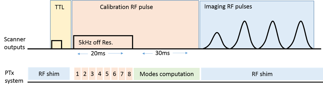
Active monitoring of induced currents is achieved using a toroidal current sensor through which the wire is passed at the body entry. Since the a-PTx system can only modify the sequence sent by the MR system, the imaging sequence, in this case the turbo spin echo (TSE), was modified by adding a 20ms off-resonance (5kHz) rectangular RF calibration pulse before the TSE train (figure 2). Real time per channel coupling measurements were made by modulating this off-resonance pulse to switch each channel on and off in turn. The resulting measurements of current amplitude and phase were then used to determine MC and NC modes.2 Synchronisation with the scanner is achieved using a TTL trigger.
Animal study
Animal experiments were conducted in vivo on sheep weighing 45 kg. Anesthesia was induced and maintained with an intravenous injection of 40 mg/kg/h ketamine and 2 mg/kg/h midazolam. Two standard nitinol guidewires of 0.89 mm diameter with polyurethane outer coating were positioned using an X-ray fluoroscopy system. The first guidewire being 180 cm long was placed in the right ventricle for visualization testing, then removed. A second guidewire 140 mm long and with a 4 mm segment of insulation stripped at the tip (for a worst-case scenario) was utilized for heating measurements. After euthanizing the animal heat measurements were repeated to investigate blood flow effects. An optical thermal probe was attached to the guidewire tip to monitor temperature. The animals were placed in the scanner in the supine position and were ventilated using a MR-compatible ventilator with a respiratory rate of 15 breaths per minute.
Imaging experiments
Following set up and piloting to determine correct image planes, performed with the array coil in a nominal quadrature mode, imaging proceeded using MC and NC settings, which were dynamically updated for each repeat of the TSE sequence. A least-squares B1+ shim optimization, operating on per channel B1+ maps, was used to determine the optimal weights for combining the NC modes. This combined NC mode (a non-heating condition) was used for anatomical imaging, with the guidewire in-situ. A balanced steady state free precession (bSSFP) sequence was used with an external cardiac trigger to produce cine images.
Results
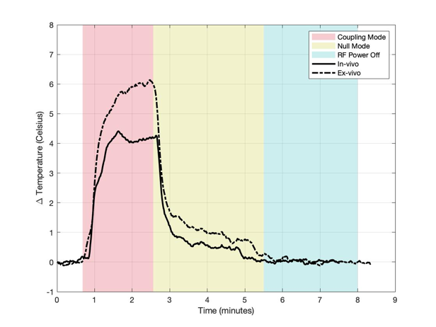
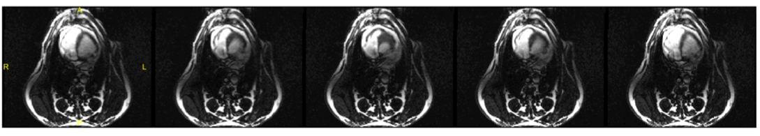
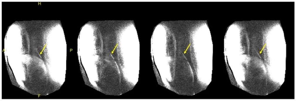
Figure 3 shows the temperature for each case using the MC mode, NC mode, and with RF power turned off, with equivalent power levels of approximately 1000W/channel. The temperature change in the presence of blood flow for each mode was 4.2°C, 0.5C, and 0.0°C, respectively. A greater temperature increase (5.9°C) was seen in the coupling mode without blood flow. Figure 4 shows selected cine frames using the B1+ shimmed NC modes. No temperature rise was observed during this acquisition. Figure 5 shows a time series of images in which the guidewire was visualised using the MC at low power during a breath cycle. The guidewire shaft is well defined (arrows) and is visible throughout the breathing motion.Discussion and Conclusion
These first in vivo results demonstrate the feasibility of using an auxiliary PTx system with a conventional scanner to perform intravascular cardiac interventions. The PTx system can actively decouple the inserted wire, and can run an imaging sequence at maximum power level producing less than 1°C temperature increase. The potential for PTx to also allow wire visualisation was also demonstrated, moving towards the goal of performing such procedures under sole MR guidance.Acknowledgements
This work was supported by the MRC developmental pathway funding scheme (MR/N027949), the Wellcome EPSRC Centre for Medical Engineering at Kings College London (WT 203148/Z/16/Z)
References
1. Nitz WR, Oppelt A, Renz W, Manke C, Lenhart M, Link J. On the heating of linear conductive structures as guide wires and catheters in interventional MRI. J Magn Reson Imaging. 2001;13(1):105-114.
2. Etezadi-Amoli M, Stang P, Kerr A, Pauly J, Scott G. Controlling radiofrequency-induced currents in guidewires using parallel transmit. Magn Reson Med. 2015;74(6):1790-1802.
3. McElcheran CE, Golestanirad L, Iacono MI, et al. Numerical Simulations of Realistic Lead Trajectories and an Experimental Verification Support the Efficacy of Parallel Radiofrequency Transmission to Reduce Heating of Deep Brain Stimulation Implants during MRI. Sci Rep. 2019;9(1):1-14.
4. Eryaman Y, Guerin B, Akgun C, et al. Parallel transmit pulse design for patients with deep brain stimulation implants. Magn Reson Med. 2015;73(5):1896-1903.
5. Godinez F, Hajnal J V, Malik SJ. Auxiliary PTx system for active control of induced RF currents in conductive guidewires. 2019:3-5.
Figures