0109
A novel active guidewire design with a curved tip geometry for interventional MRI applications under 0.55T.1Cardiovascular Branch, Division of Intramural Research, National Heart Lung and Blood Institute, National Institutes of Health, Bethesda, MD, United States, 2Institute of Biomedical Engineering, Bogazici University, Istanbul, Turkey, 3Transmural Systems, Andover, MA, United States
Synopsis
A clinical-grade active MRI 0.035” guidewire design with a curved distal tip geometry and continuous shaft signal ensuring the mechanical and electrical safety, was introduced. Proposed design was tested in-vitro and in-vivo for MRI visibility and mechanical performance, and in-vitro for RF induced heating.
INTRODUCTION
A guidewire is a fundamental tool for image-guided minimally invasive procedures. Previously, it was shown that an active guidewire design based on a monopole loopless antenna is ideal for interventional MRI applications thanks to its simplicity, miniaturization and high near-field SNR1-4. The only drawback of the loopless antenna design is that the sensitivity profile gradually decreases to zero towards to the tip, Therefore, the distal end of the guidewire becomes invisible under MRI. This problem needs to be fixed to ensure operational safety. Extending the antenna whip and packing the extended conductor as a tight-pitched coil helps to overcome this problem3-5. A clinical grade MRI guidewire must have sufficient mechanical properties to navigate in tortuous vasculature ensuring the electrical and mechanical safety in addition to the continuous conspicuity6. However, the literature lacks an active guidewire design having a curved distal tip with a complete whip conspicuity. In this study, we introduce a novel active MRI guidewire design suitable for clinical applications, having a curved tip and comparable mechanical characteristics to the commonly used commercial guidewires, and a continuous sensitivity profile along the whip, providing a complete tip geometry information under a prototype 0.55T MRI system.METHODS
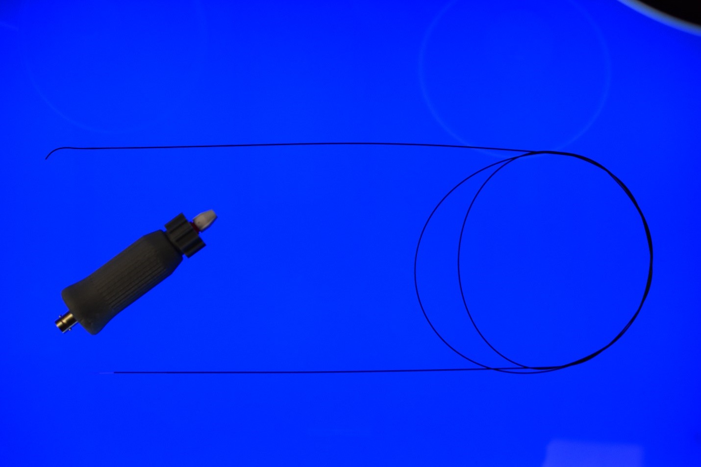
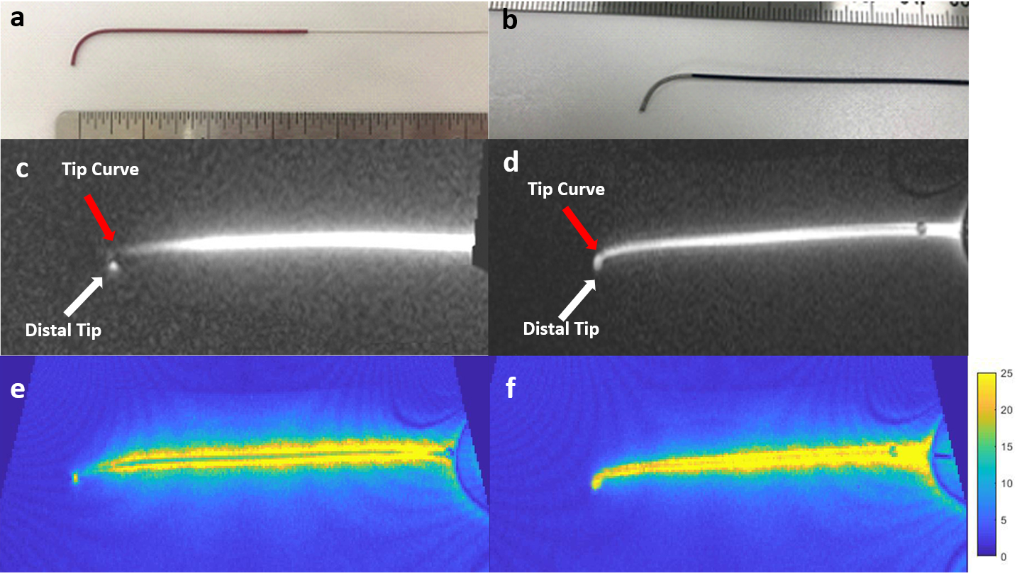
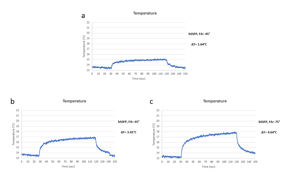
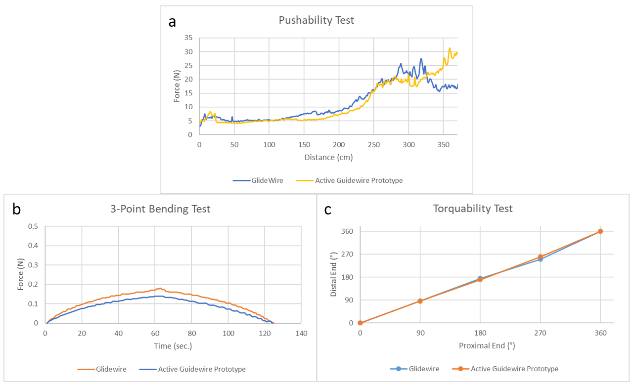
The active guidewire was designed and manufactured using medical grade MRI compatible materials. The length is 162,5 cm and the diameter is 0.89 mm (0.035”) for the compatibility with the conventional cardiovascular catheters. A nitinol wire with a changing profile (0.127mm min. and 0.508mm max. diameter) and a curved tip geometry (Trutech, MI, USA) served as the inner conductor of the monopole antenna. The inner conductor was coated with a Pebax tube (Microcatheter Components, NH, USA) and placed in a nitinol hypotube (Memry, CT, USA) which is used as the shield of the coaxial shaft. The inner conductor was extended 37.5 cm beyond the nitinol hypotube to form the whip. A tightly wound insulated alloy solenoid coil was electrically connected to the distal end of the whip. The subassembly was finally insulated with a 0.8mm ID, 0.89mm OD Pebax tube. The coaxial shaft was connected to a tune/match circuit via a detachable connector and then to the MRI scanner, to enable the catheter exchange during an interventional procedure which is expected from the conventional guidewires (Figure 1). A 0.076mm diameter MP35N wire with 0.02mm insulation thickness and a 0.05mm diameter 35N LT wire with 0.005mm insulation thickness were used to form 0.71mm OD coils (Figure 2.a and 2.b) to assess the effects of the number of turns and the coil length on the signal intensity. Coil length was optimized for the continuous whip signal providing the curve information. Active guidewire prototypes were tested in-vitro for MRI visibility in a gel phantom prepared per ASTM 2182-11a7 using a bSSFP sequence (TE/TR=1.11/4ms, flip angle=45°, FOV=400mm, matrix=192×144, slice thickness=8mm) at a prototype 0.55T MRI Scanner (Siemens, Erlangen, Germany). After the visibility tests, the guidewire design with MP35N coil was discarded and RF induced heating performance tests were performed using the same bSSFP sequence with additional 65° and 75° flip angles. In-vitro mechanical performance was assessed via push-ability, 3-point bending and torquability tests and compared to a commercial clinical-grade guidewire (Glidewire, Terumo, NJ, USA). In-vivo MRI visibility and mechanical performance were tested in a swine using the same bSSFP sequence used for in-vitro imaging tests, at 0.55T, complying with the local animal care and use committee guidelines. the active guidewire signal was artificially highlighted on the image using a custom real-time MRI reconstruction tool.RESULTS
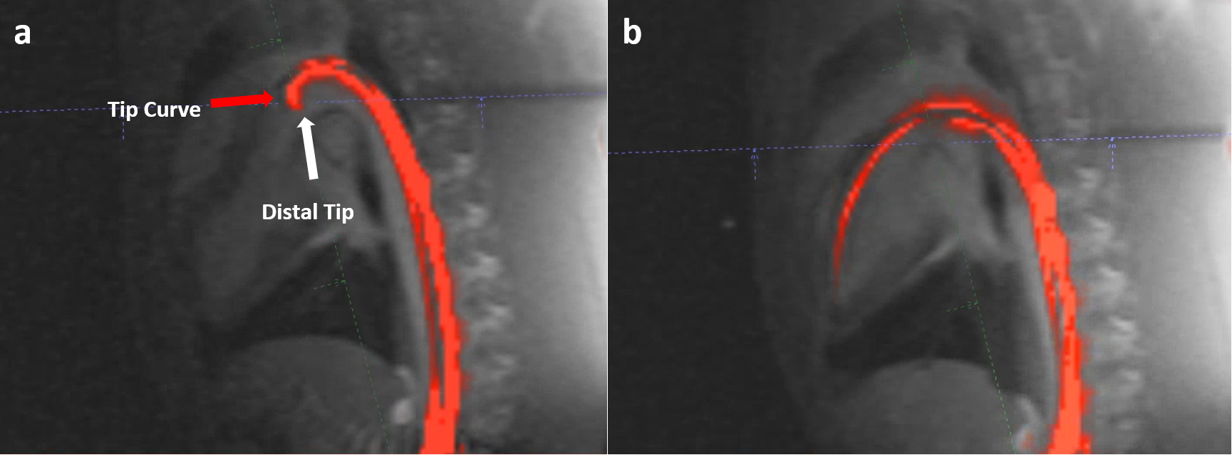
After the coil length optimization, 50mm long MP35N solenoid coils provided a distinct tip signal, and 14mm long 35N LT coils provided a continuous signal for the entire whip (figure 2.c and 2.d). RF induced temperature rise at the guidewire tip (the hot spot) was 1.64C°, 3.41C° and 4.64C° for the 45°, 65° and 75° flip angles, respectively (Figure 3). Mechanical properties of the guidewire prototype were comparable to the commercial equivalent (Figure 4). Left ventricle of the swine heart was accessed retrograde via femoral entry using the active guidewire prototype, successfully (Figure 5).DISCUSSION
Extended whip design by connecting a solenoid coil helps to balance and even reduce the signal intensity attenuation towards the distal end of the whip. The number of turns and the length of the tip coil alter the effective wavelength so that the sensitivity profile of the whip. The desired signal signature can be obtained adjusting these parameters. The curved tip geometry of a guidewire is found very helpful by the operators to navigate through the vascular system. The distinct tip signal of the MP35N coils lacked the tip geometry information while the 35N LT coils provided continuous tip curvature signal which is crucial for operational safety and expected by the operators. The detachable connector allows intra-operational device exchanges over the proposed active guidewire design.CONCLUSION
In this study, we have successfully developed a clinical-grade, low-field active MRI guidewire design with a curved tip geometry and continuous whip signal ensuring the mechanical and electrical safety which is essential to be used for clinical MRI guided minimally invasive operations.Acknowledgements
We would like to acknowledge the assistance of Siemens Healthcare in the modification of the MRI system for operation at 0.55T under an existing cooperative research agreement (CRADA) between NHLBI and Siemens Healthcare.This study was supported by the Division of Intramural Research, National Heart, Lung, and BloodInstitute, National Institutes of Health, USA (Z01-HL005062 and Z01-HL006061).References
1. Ocali O, Atalar E. Intravascular magnetic resonance imaging using a loopless catheter antenna. Magn Reson Med. 1997;37(1):112-8.
2. Kocaturk O, Kim AH, Saikus CE, Guttman MA, Faranesh AZ, Ozturk C, et al. Active two-channel 0.035'' guidewire for interventional cardiovascular MRI. J Magn Reson Imaging. 2009;30(2):461-5.
3. Sonmez M, Saikus CE, Bell JA, Franson DN, Halabi M, Faranesh AZ, et al. MRI active guidewire with an embedded temperature probe and providing a distinct tip signal to enhance clinical safety. J Cardiovasc Magn Reson. 2012;14:38.
4. Susil RC, Yeung CJ, Atalar E. Intravascular extended sensitivity (IVES) MRI antennas. Magn Reson Med. 2003;50(2):383-90.
5. Karmarkar PV, Kraitchman DL, Izbudak I, Hofmann LV, Amado LC, Fritzges D, et al. MR-trackable intramyocardial injection catheter. Magn Reson Med. 2004;51(6):1163-72.
6. Rogers T, Lederman RJ. Interventional CMR: Clinical applications and future directions. Curr Cardiol Rep. 2015;17(5):31.
7. International A. ASTM 2182-11a Standard Test Method for Measurement of Radio Frequency Induced Heating On or Near Passive Implants During Magnetic Resonance Imaging.
Figures