0106
Three-dimensional magnetic resonance acoustic radiation force imaging in the breast1Radiology and Imaging Sciences, University of Utah, Salt Lake City, UT, United States, 2Biomedical Engineering, University of Utah, Salt Lake City, UT, United States, 3Image Guided Therapy, Pessac, France, 4Institut Bergonie, Bordeaux, France
Synopsis
3D MR acoustic radiation force imaging (MR-ARFI) is a useful treatment planning and monitoring tool for magnetic resonance guided focused ultrasound (MRgFUS) treatments in the breast. MR-ARFI displacement is easily visualized in fat, fibroglandular and tumor tissues, allowing for accurate localization of the ultrasound beam and quantitative tissue assessment. The potential formation of standing shear waves in the breast requires careful optimization of the pulse sequence to ensure clear visualization of the radiation force displacement point. This effect is shown in both human breast and phantom data.
Introduction
Recently there has been increased interest in minimally invasive techniques as a way to treat breast cancer. MRgFUS is one of the most attractive minimally invasive procedures as it can safely and efficaciously treat breast tumors non-invasively with real-time image monitoring (1). Current clinical MRgFUS treatments use the proton resonance frequency (PRF) shift method to monitor temperature during MRgFUS treatments, but PRF thermometry cannot monitor temperature in adipose tissues. Alternatively, MR acoustic radiation force imaging (MR-ARFI) can be used to image and measure the displacement due to the radiation force of the focused ultrasound beam in all tissues, including fat (2). Because breasts have patient-specific degrees of heterogeneity, with all breasts containing both aqueous and adipose-based tissues, the use of MR-ARFI during breast MRgFUS treatments can provide accurate treatment targeting and quantitative displacement feedback. This work investigates the in vivo use of a 3D MR-ARFI sequence in human breast tissue. The effect of MR-ARFI parameters on the measured displacement and shear wave propagation is also investigated in a homogeneous gelatin phantom.Methods
A first-in-human prospective single center study is treating patients with clinically non-palpable stage T0 breast cancer (tumor < 15 mm) witha breast MRgFUS system(3-5) (Figure 1) installed in a 1.5T MRI scanner (Aera, Siemens, Erlangen, Germany). At the time of submission, ten patients have been treated. In 6 of these patients, 3D MR-ARFI was used to localize the focal spot of the focused ultrasound beam and accurately target the tumor before the MRgFUS ablation was performed. The 3D MR-ARFI sequence (6) (Figure 2) applies bipolar motion encoding gradient lobes (MEG) interleaved between TR's without and with ultrasound pulses applied (TR = 20-45 ms, TE = 14 ms, FOV = 256x192x36 mm, resolution = 2x2x3 mm, 25° flip angle, ETL = 1, 40 mT/m MEG amplitude, 5 ms MEG lobe duration, 5 ms FUS pulse length at 100 acoustic W, 5 ms MEG lobe duration). Slices were placed obliquely, perpendicular to the axis of ultrasound beam propagation. The effect of TR on the measured MR-ARFI displacement pattern including the standing shear wave pattern was evaluated by applying the same MR-ARFI sequence in a breast-shaped gelatin phantom (125 bloom) with equivalent sequence parameters, except imaging was performed at 3T, a 60mT/m MEG amplitude was used and the TR was incrementally increased from 19 to 51 ms to observe changes in the standing wave pattern.Results
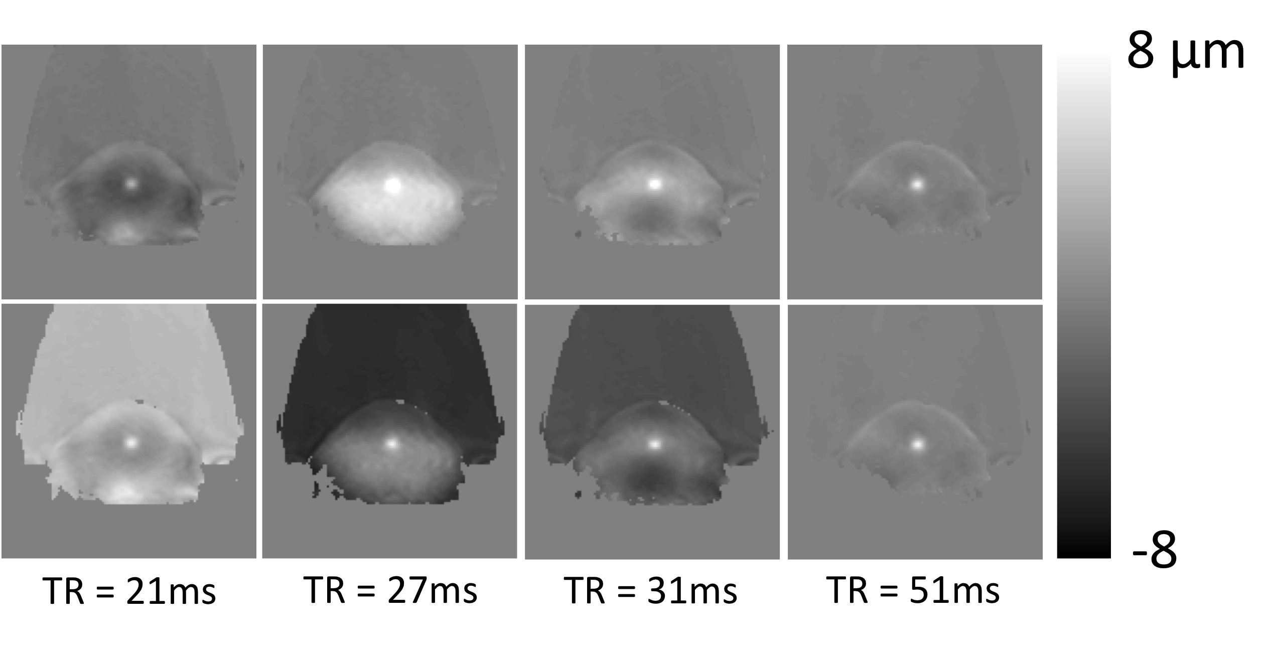
Sixteen 3D MR-ARFI measurements were successfully obtained from the 6 breast cancer patients. Measured tissue displacement ranged from 10.5 to 51.7 μm. Patients were not sedated during the MRgFUS ablation procedure and all patients felt no pain or any sensation during the MR-ARFI measurement. Figure 3 shows MR-ARFI measurements both in the acquired slice orientation perpendicular to the ultrasound beam and in a reformatted view, overlaid on a contrast-enhanced T1-weighted image in 2 representative patients. In both orientations, it is clear that tissue displacement in addition to the initial targeted ARFI location is encoded in images. The spatial distribution of this additional displacement appears to be TR dependent. This can be more clearly observed in the phantom MR-ARFI results in Figure 4, at TR = 21, 27, 31 and 51 ms. The 1st row depicts the MR-ARFI displacement map. While the central displacement from the ARF push is visible, similar to the breast cancer patients, there is additional TR dependent recorded displacement in the surrounding regions. The 2nd row shows the same images from the 1st row with an offset added to display the maximum peak at the same displacement.Discussion and Conclusions
Because tissue displacement can be observed in all tissue types, MR-ARFI measurements are an effective measurement that is useful during both the planning and monitoring of breast MRgFUS ablation treatments. The central displacement can be easily visualized, as shown in Figure 3. However, in addition to the central ARF displacement, shear waves can be encoded into the MR image phase, particularly at shorter TR values. In addition, due to asymmetry, the reflected shear wave can refocus at a point that is not at the location of the original focused ultrasound pulse, as seen in the 3rd columns of Figure 4 when TR = 31ms. The 2nd row demonstrates that the desired ARFI point can be seen with near equal conspicuity if the image is offset to reduce the standing wave amplitude at the ARFI point. The presence of standing shear waves decreases with increasing TR. While a short TR is ideal for fast acquisitions, the standing shear wave patterns tend to be larger for short TR acquisitions, requiring the user to be aware of the presence of these encoded standing waves so that interpretation of the MR-ARFI displacement results is not affected.Acknowledgements
This project was funded through NIH grants R37CA224141, S10OD018482 and the Laboratory of Excellence TRAIL ANR-10-LABX-57.References
1. Schmitz AC, Gianfelice D, Daniel BL, Mali WP, van den Bosch MA. Image-guided focused ultrasound ablation of breast cancer: current status, challenges, and future directions. Eur Radiol. 2008. PubMed PMID: 18351348.
2. Bour P, Marquet F, Ozenne V, Toupin S, Dumont E, Aubry JF, Lepetit-Coiffe M, Quesson B. Real-time monitoring of tissue displacement and temperature changes during MR-guided high intensity focused ultrasound. Magn Reson Med. 2017. doi: 10.1002/mrm.26588. PubMed PMID: 28090656.
3. Payne A, Merrill R, Minalga E, Vyas U, de Bever J, Todd N, Hadley R, Dumont E, Neumayer L, Christensen D, Roemer R, Parker D. Design and characterization of a laterally mounted phased-array transducer breast-specific MRgHIFU device with integrated 11-channel receiver array. Med Phys. 2012;39(3):1552-60. doi: 10.1118/1.3685576. PubMed PMID: 22380387; PMCID: 3306440.
4. Minalga E, Payne A, Merrill R, Todd N, Vijayakumar S, Kholmovski E, Parker DL, Hadley JR. An 11-channel radio frequency phased array coil for magnetic resonance guided high-intensity focused ultrasound of the breast. Magn Reson Med. 2013;69(1):295-302. doi: 10.1002/mrm.24247. PubMed PMID: 22431301; PMCID: PMC3382025.
5. Svedin BT, Beck MJ, Hadley JR, Merrill R, de Bever JT, Bolster BD, Jr., Payne A, Parker DL. Focal point determination in magnetic resonance-guided focused ultrasound using tracking coils. Magn Reson Med. 2017;77(6):2424-30. doi: 10.1002/mrm.26294. PubMed PMID: 27418429; PMCID: PMC5237622.
6. de Bever JT, Odeen H, Hofstetter LW, Parker DL. Simultaneous MR thermometry and acoustic radiation force imaging using interleaved acquisition. Magn Reson Med. 2018;79(3):1515-24. doi: 10.1002/mrm.26827. PubMed PMID: 28795419; PMCID: PMC5775920.
Figures
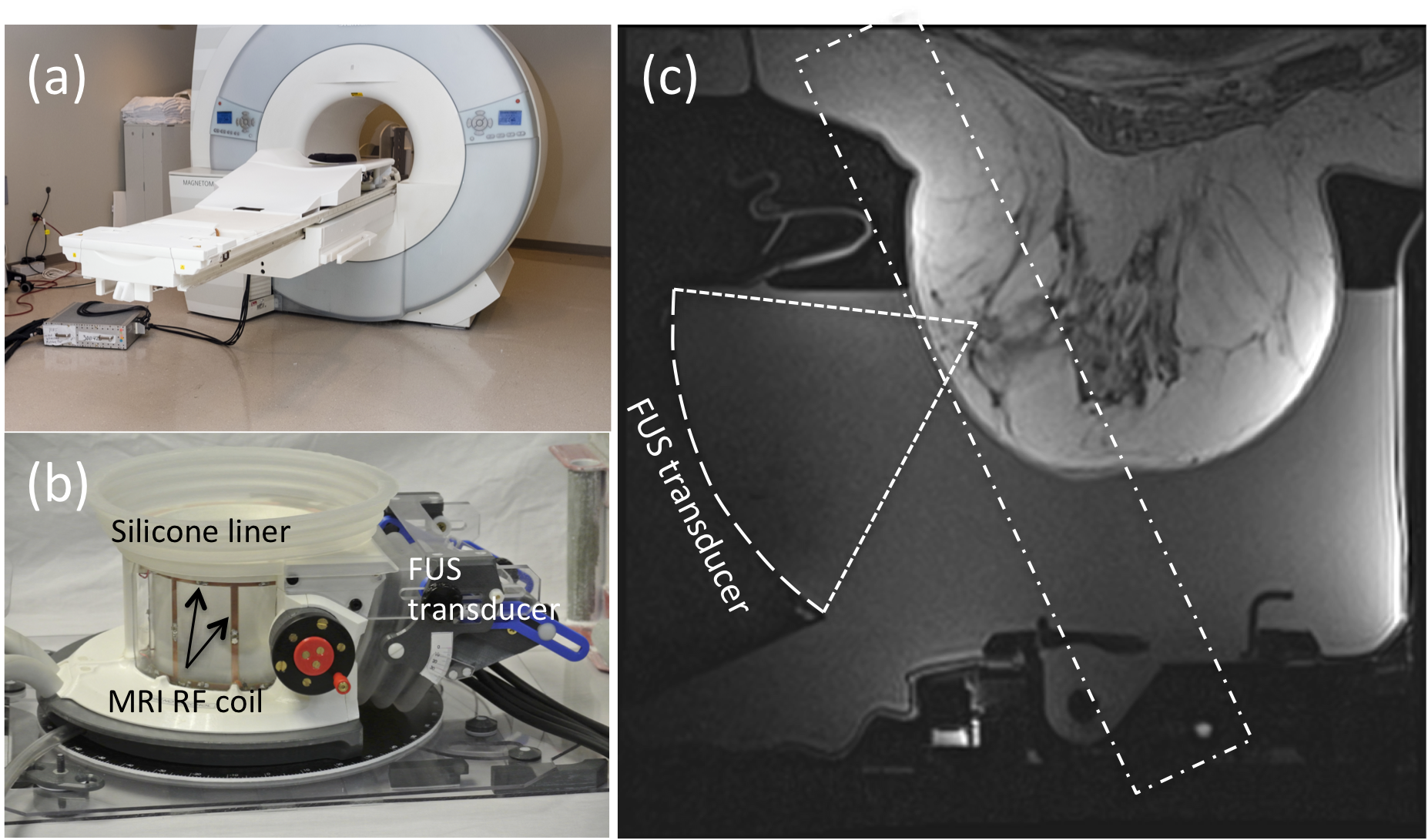
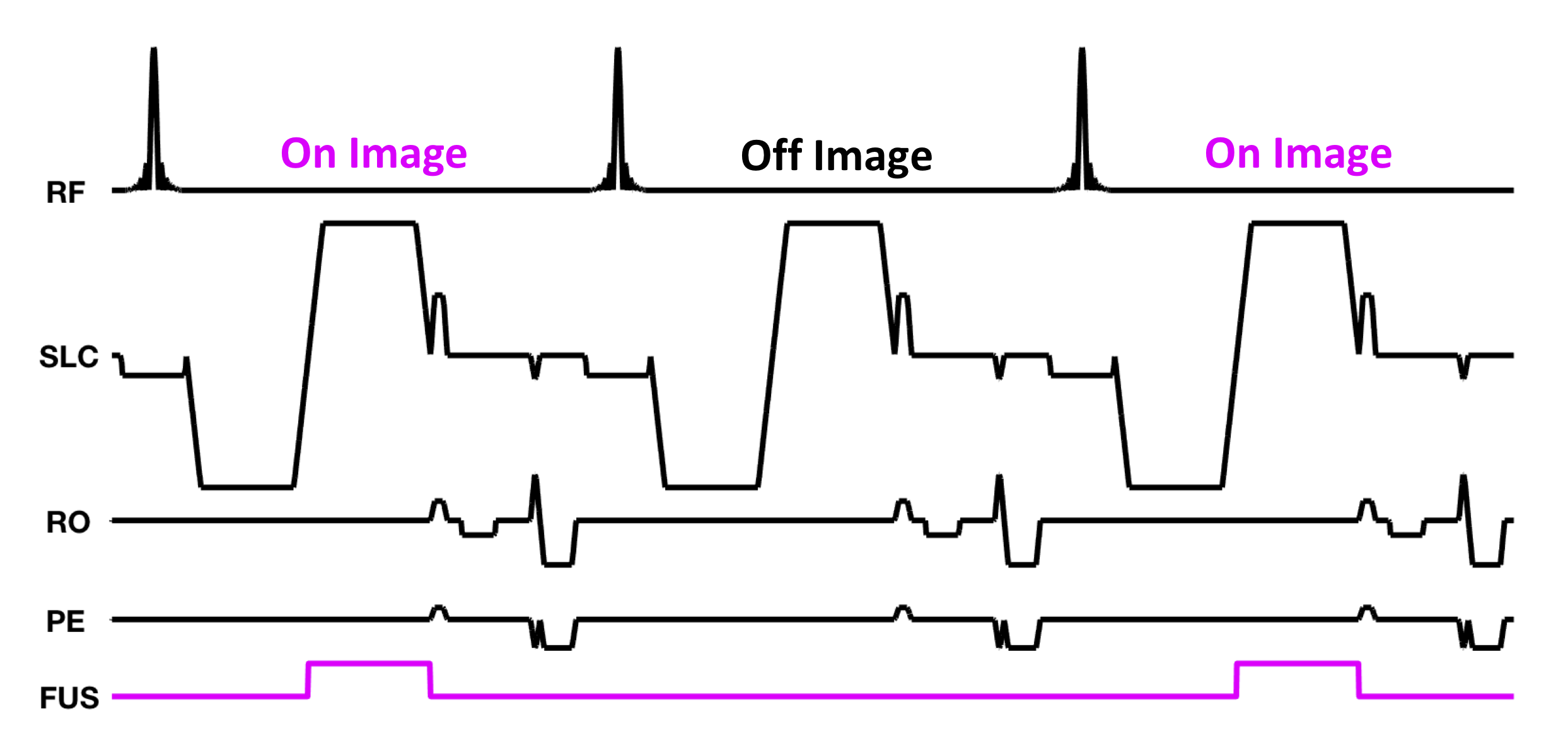
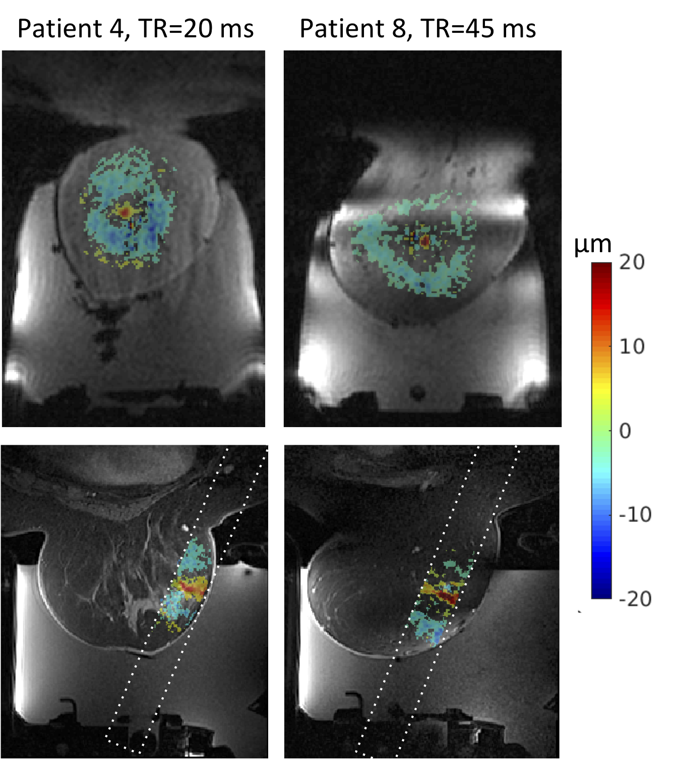
Figure 3: 3D MR-ARFI results for subjects 4 (left) and 8 (right). The displacement pattern in the oblique coronal acquisition plane is shown on the top row and the displacement pattern overlaid on a contrast enhanced T1w image is shown on the bottom row.