0006
Toward “plug and play” prospective motion correction for MRI by combining observations of the time varying gradient and static vector fields.1Biomedical Engineering Research Centre, Division of Biomedical Engineering, Department of Human Biology, Faculty of Health Sciences, University of Cape Town, Cape Town, South Africa, 2Athinoula A. Martinos Center, Massachusetts General Hospital, Charlestown, MA, United States, 3Radiology, Harvard Medical School, Boston, MA, United States, 4Cape Universities Body Imaging Centre, Cape Town, South Africa, 5Neuroscience Institute, Faculty of Health Sciences, University of Cape Town, Cape Town, South Africa
Synopsis
Introducing additional hardware to measure patient motion allows for fast and accurate prospective motion correction that has minimal or no impact on the imaging pulse sequence. This does however entail additional setup that in some cases may be challenging to translate into a dynamic clinical setting. In this work we explore the use of an intelligent marker - a Wireless Radiofrequency-triggered Acquisition Device (WRAD) - for prospective motion correction. This new approach incorporates all additional hardware (besides a wireless receiver) into the marker that is attached to the subject. Initial results show improved image quality without scanner specific calibration.
Purpose
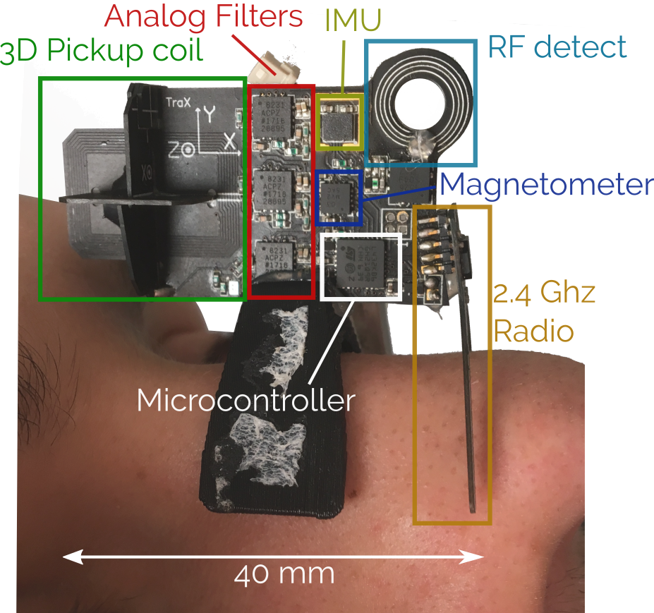
Previously, we developed a Wireless Radio frequency triggered Acquisition Device (WRAD1) - an intelligent wireless ‘marker’ capable of self-synchronizing to the gradient time frame with sub-microsecond precision (Figure 1). The WRAD measures the magnetic spatial encoding of the gradient coils, through induction, during a series of sinusoidal blips lasting 880 μs (3D pickup coil, Figure 1). This simplifies cross-calibration and miniaturization so that the additional hardware required for digitizing and processing the signals can be embedded within the ‘marker’ itself. By doing so, the scanner is in its original state when the device is removed. The device can therefore be thought of as “plug and play”, and used only when it is needed. Although the hardware requirements for sampling of the gradient fields through induction are simplified, the interpretation of these measurements is more challenging because they produce a 3-dimensional vector field. To alleviate this problem the WRAD incorporates additional sensors that over constrain the solution. In this work2 we demonstrate how this over-constrained data can be fused to accurately track and correct subject motion, as well as imperfections in the WRAD and gradient coils whilst controlling the output variance of motion parameters.Methods
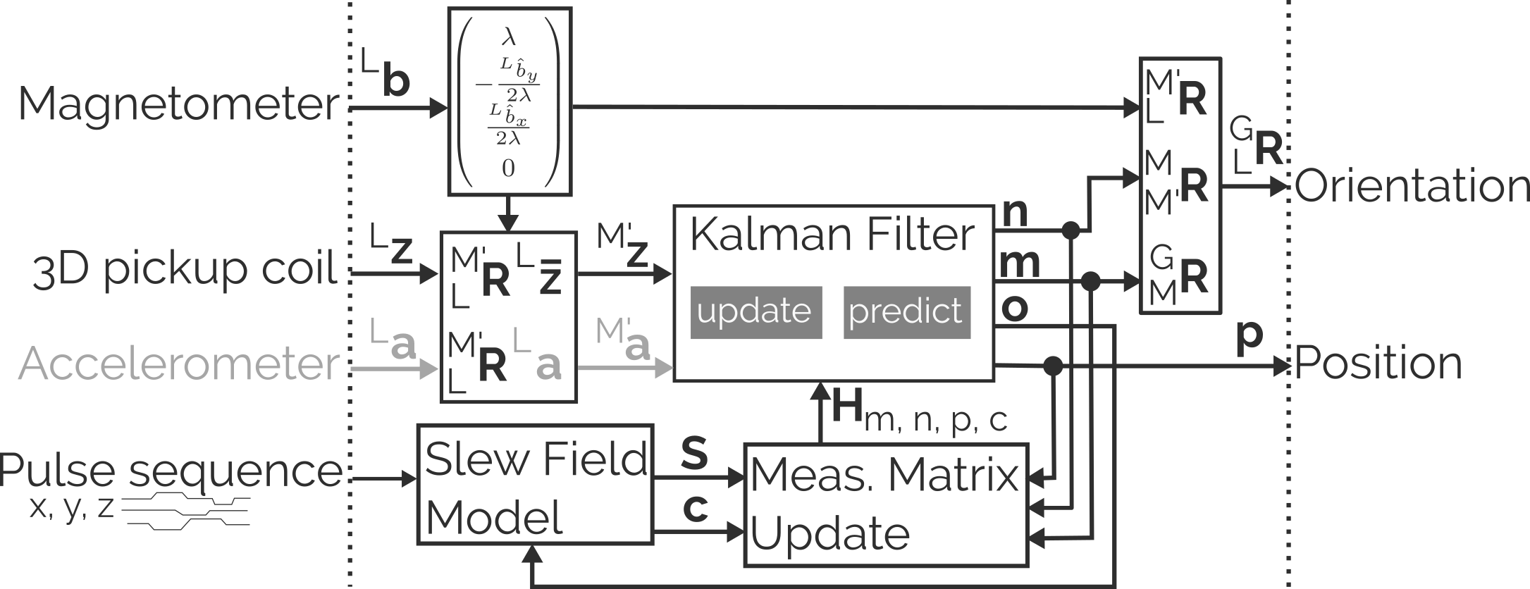
The filter we propose relies heavily on a precise estimate of the direction of the static magnetic field (Lb), obtained from a 3-axis magnetometer mounted on the WRAD (Magnetometer, Figures 1-2). We use this estimate to rotate the voltage vectors (3D pickup coils, Figure 2) from the WRAD frame (L) into an intermediate reference frame (M’) that has its z-axis aligned with the static magnetic field. This transform is more intuitively written in unit-quaternion form3:, whereThe z-component of the gradient field contributes to the NMR spatial encoding. It is therefore possible to treat the z-component of each voltage in the same way as a frequency shift of an NMR field probe. The direction of the xy-component of the voltage vectors in the intermediate frame are used to encode the remaining degree of freedom in rotation of the WRAD with the filter state n (Figure 2): .
The amplitude of the xy-component of the vector encodes position in a different spatial dimension to its respective z-component (NMR) encoding. For example, the x-gradient coil encodes the z-displacement in the x-direction of the gradient frame (G). The vector field (f) produced by the changing gradients (s) encode the position (p) as follows: where
The bias state vector c (Figure 2) models mechanical misalignments of the x and y gradient coils with respect to the z-gradient coil in the z-direction and the z-gradient coil with respect to the x-gradient coil in the x-direction and y-gradient coil in the y-direction.
We account for a small bias in the magnetometer that could project into the results by introducing a state vector m (Figure 2) that represents a small rotation about the MRI scanner’s x and y axes.
The states m, n, p and c are then tracked using a modular Kalman filter. Here we assume the system is stationary, and therefore treat the other states as constant when updating each vector.
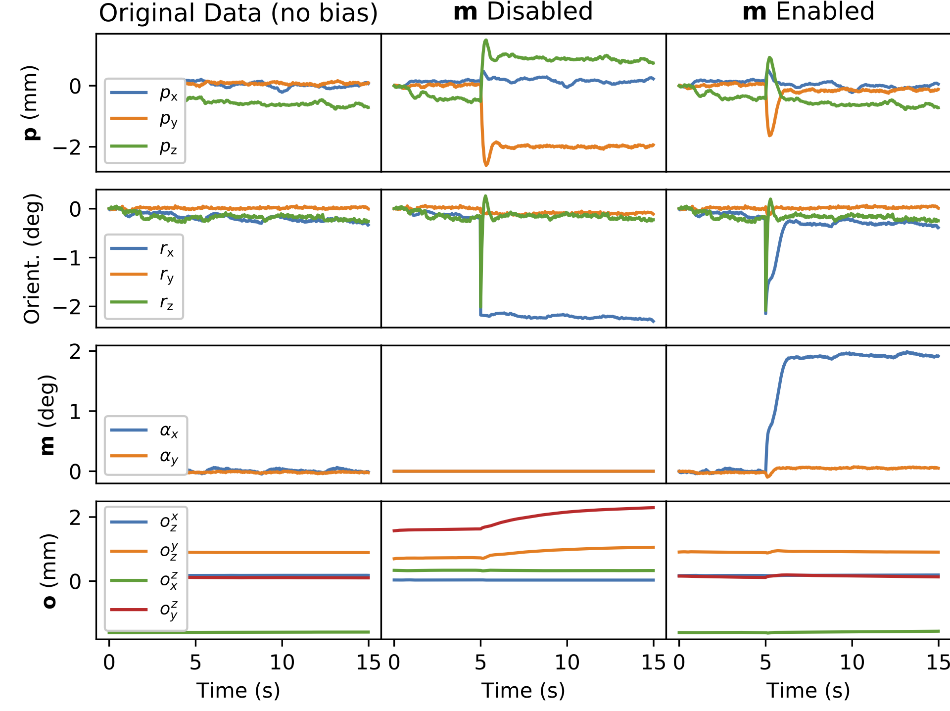
Experiments: 1) A synthetic rotation of the magnetometer with respect to the 3D pickup coil was introduced 5 seconds into a scan to test the estimation of the bias rotation state m.
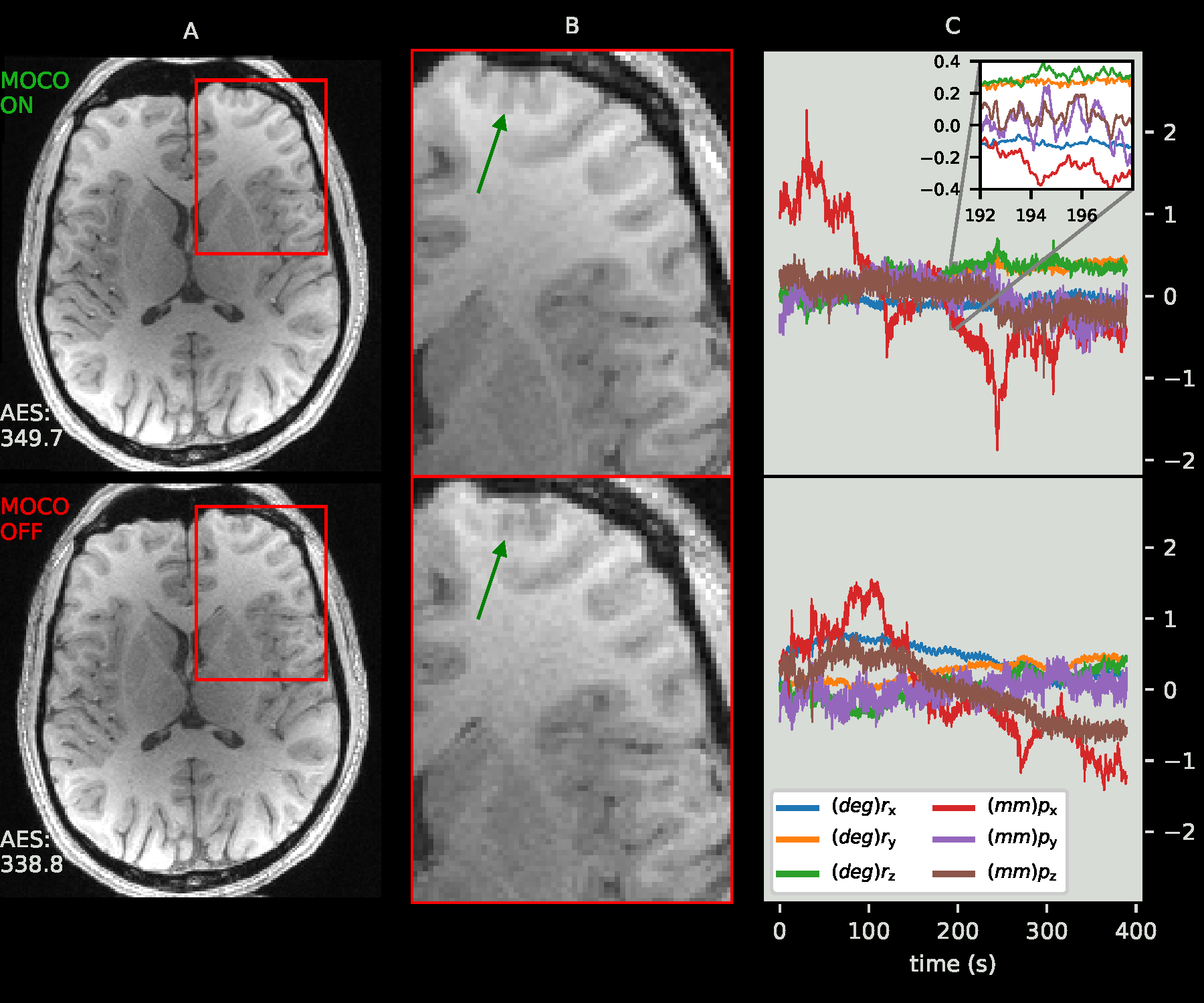
2) Prospective motion correction of involuntary motion using encoding from only the X and Z gradient coils (sinusoidal navigator; duration of 600 μs per update; 120 T/m/s peak slew rate).
3) Prospective motion correction of deliberate motion using data from all 3 gradient coils (sinusoidal navigator; duration of 880 μs per update; 120 T/m/s peak slew rate).
Results
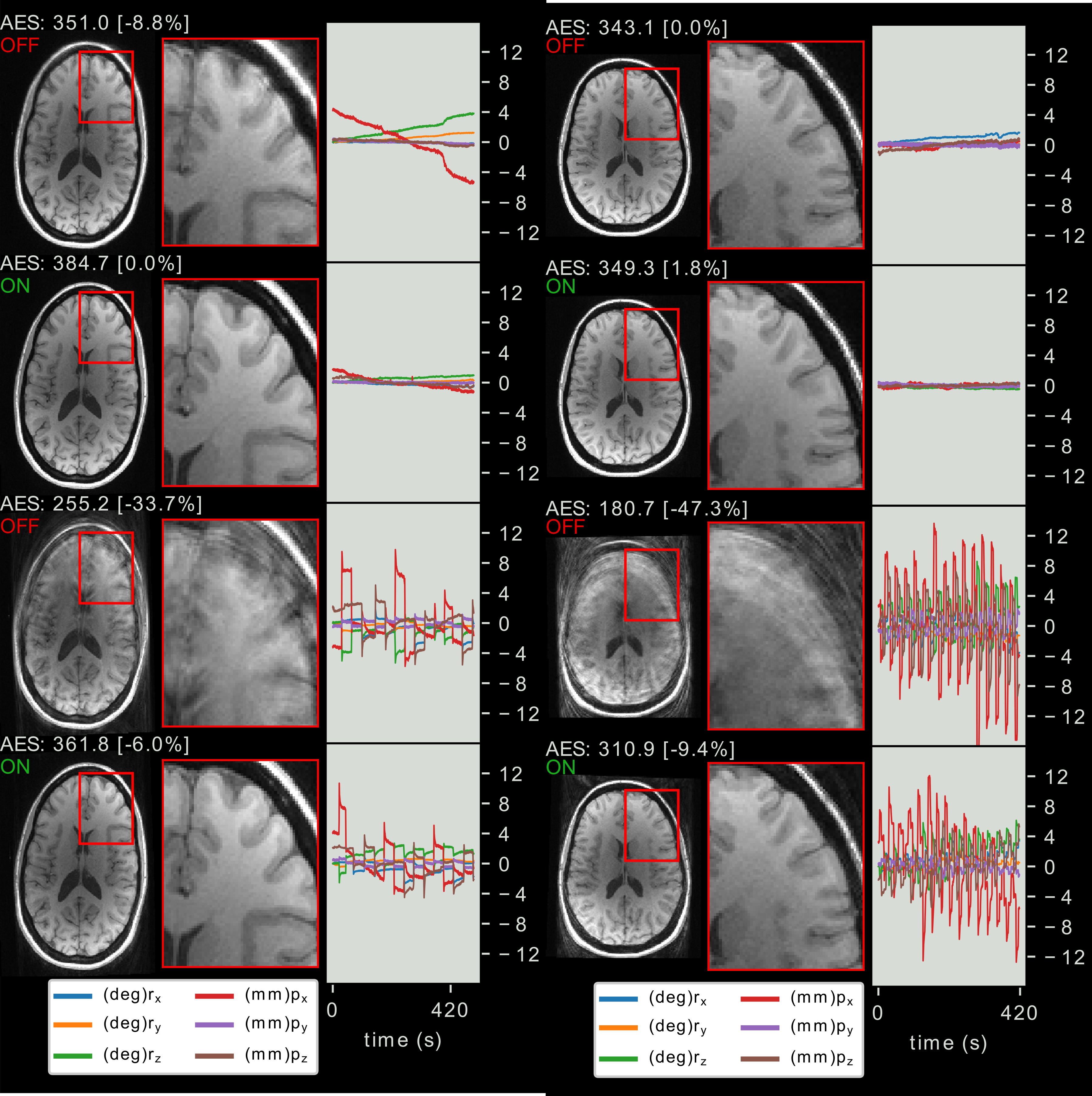
1) The filter effectively tracks biases caused by magnetometer misalignment (m Enabled, Figure 3).2) A noticeable improvement in image quality is achieved, particularly in the frontal regions of the brain, even when the subject moved very little during the acquisition (Figure 4).
3) Prospective motion correction dramatically improves image quality for the case of deliberate motion even in the case of strong frequent motion (Figure 5).
Discussion
The proposed method requires a once-off calibration of a global scaling parameter (Volts/mm). This can be considered a device specific calibration. We therefore expect that the same WRAD could be used on multiple scanners without additional setup.Conclusion
The WRAD provides a simple and effective way of enabling prospective motion correction on an MRI scanner without hardware modifications, calibrations or mounting considerations – such as line of sight. Pulse sequence modifications are, however, still necessary in the current implementation.Acknowledgements
This work was supported in part by the National Institutes of Health under grants R01HD085813, R01HD093578, R21AG046657, R01HD071664 and R21MH096559, the Bertarelli Foundation, the NRF/DST through the South African Research Chairs Initiative and the University of Cape Town through the RCIPS Explorer fund EX15-009.References
1) A. van Niekerk, E. Meintjes and A. van der Kouwe, "A Wireless Radio Frequency Triggered Acquisition Device (WRAD) for Self-Synchronised Measurements of the Rate of Change of the MRI Gradient Vector Field for Motion Tracking," in IEEE Transactions on Medical Imaging, vol. 38, no. 7, pp. 1610-1621, July 2019.
2) van Niekerk, A, van der Kouwe, A, Meintjes, E. Toward “plug and play” prospective motion correction for MRI by combining observations of the time varying gradient and static vector fields. Magn Reson Med. 2019; 82: 1214– 1228. https://doi.org/10.1002/mrm.27790
3) R. G. Valenti, I. Dryanovski and J. Xiao, "A Linear Kalman Filter for MARG Orientation Estimation Using the Algebraic Quaternion Algorithm," in IEEE Transactions on Instrumentation and Measurement, vol. 65, no. 2, pp. 467-481, Feb. 2016.
Figures