MR Linac: Implementations & Challenges
Synopsis
Key hardware features and requirements of integrated MR-guided Linac-based radiotherapy systems and practical implementations are explained.
Introduction and scope
The integration of an MRI scanner and a Linac based external beam radiotherapy system, with the objective to image the irradiated part of the patient while the radiation is being applied is a challenging task. This abstract describes the major engineering issues of such an integrated MR-Linac system and presents three different solutions that have proven to work. The main focus will be MRI hardware. The clinical use of such systems is beyond the scope of this presentation.General requirements
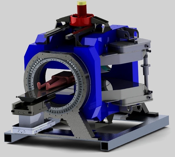
In all practical integrated MR-Linac systems the patient is lying on a horizontal table and the radiation source can be rotated around an axis in the head-feet direction of the patient. The radiation is collimated by means of a variable aperture diaphragm (the so-called Multi Leaf Collimator, MLC), to a field with a lateral extension of 200-300 mm in both directions. Dose is determined by the setting of the MLC and the dose rate of the radiation source. For MRI guidance of the radiation treatment, one needs the static, gradient and RF fields needed to perform MR imaging in the same volume as where the radiation is being applied. The MRI hardware needed to generate these fields has to allow the radiation to pass through with as little attenuation as possible and such that the dose at the tumor is predictable to within a few percent.Making the MRI system transparent to radiation
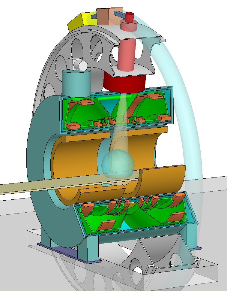
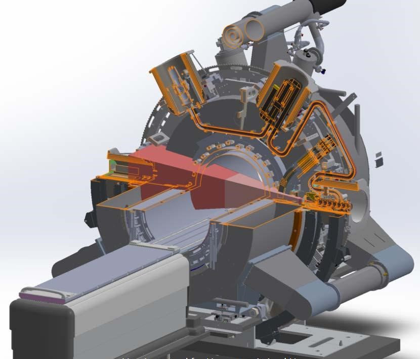
In the MR-Linac systems developed by Elekta/Philips and by ViewRay the MRI magnet is cylindrical and the plane of rotation of the linac is the z=0 plane of the MRI system. Thus the radiation beam is perpendicular to the static field of the MRI system. In both systems the field generating coils have a sufficiently large gap between them that the beam can pass through. The cryostat of the ViewRay system has an air-gap in the beam region whereas in the Elekta/Philips system the beam has to pass through thin cryostat walls. In either case, there will be some radiation exposure of the cold mass. The power is so small that it will never quench the magnet but the exposure can lead to radiation damage of construction material and components. In the system developed at the Cross Cancer Institute (MagnetTX) the radiation beam reaches the patient through a central hole in the pole of a yoke-based vertical field MRI magnet. Thus the beam is parallel to the field. In order to irradiate from multiple angles, the entire scanner and the Linac are made to rotate around the patient.
Avoiding magnetic field exposure of the Linac
The magnetic field at the Linac has to be kept small and stable. If it is too high (typically above 0.5 millitesla), no electrons can escape from the cathode and the tube stops working. If the field is not stable, the position of the focal spot of the radiation will vary and this affects dose predictability. In the Elekta/Philips system, which has a central field of 1.5 tesla, an active shielding configuration with four shield coils keeps the field at the Linac sufficiently small. The 0.35 tesla ViewRay system, does not have such active shielding. Instead the Linac and at other field-sensitive beam generating components are shielded with local high-permeability shielding. The CCI system also relies on passive shielding of the Linac. The Linac can also be disturbed by magnetic fields induced in magnetic material in the walls of the radiation bunker when this is magnetized by the MRI magnet. Avoiding such wall effects is another motivation for optimizing the magnet's external field. Where it is inevitable that bunker wall material can get magnetized (especially in the floor below the system), it may be necessary to cut the magnetic material out and replace it by something non-magnetic.Avoiding field distortion and modulation in the MR scanner
Reducing the external field of the magnet also avoids that magnetic material belonging to the beam generation system gets magnetized and adds to the field in the MRI imaging volume. In order to be able to make good quality MR images while the Linac is rotating the field contribution from the Linac gantry has to be made rotationally symmetric to within 100 nT. This may require local compensation of magnetic parts such as MLC servo motors. Apart from the static field generated by magnetic material on the Linac gantry, the beam generation system can also produce AC fields, for example from large currents flowing in power cables. Careful design of cabling and slip-rings has to keep the amplitude of such mains-frequency fields below a few nanotesla in the imaging volume.Avoiding RF noise from the Linac
Linacs generate enough broad-band RF noise to spoil an MRI image. RF shielding has to prevent this. In the Elekta/Philips system, this is accomplished by making the MR magnet an integral part of the RF room shield and to place all of the beam generation components on the dirty side of this shield. The other MR-Linac implementations use local RF shielding around the noisy components. Some RF-noise will be generated by the free electrons that result from the interaction between the ionizing radiation and the patient and other materials. This leads to some reduction in image quality; at 1.5 tesla/64 MHz it is hardly visible.Gradient coil with radiation window
The gradient coil needs a sufficiently large opening, free of conductors, that the radiation can pass through. A thin radiation-transparent epoxy cylinder to keep the two coil halves together is allowed. Due to the gap the efficiency of an MR-Linac gradient coil is significantly lower than of a standard coil of the same diameter. The hole in the stray-field shielding may also lead to some eddy-currents in conducting parts outside the coil.RF transmit and receive coils
If the coils are made from very thin copper foil on thin support structures the radiation absorption is small. Lumped components such as capacitors, amplifiers and cables have to be kept out of the radiation field. With proper design, the performance of radiation-transparent RF coils is similar to that of standard RF coils. Most RF components are sufficiently radiation resistant to survive exposure to the treatment radiation.Acknowledgements
No acknowledgement found.References
BW Raaymakers, J W Lagendijk, JA Overweg, J Kok, J E Raaijmakers, E Kerkhof, R van der Put, I Meijsing, S Crijns, F Benedosso, M van Vulpen, H W de Graaff, J Allen, K Brown (2009). Integrating a 1.5 T MRI scanner with a 6 MV accelerator: Proof of concept. Physics in medicine and biology. 54. N229-37.
Mutic, Sasa & F Dempsey, James. (2014). The ViewRay System: Magnetic Resonance-Guided and Controlled Radiotherapy. Seminars in radiation oncology. 24. 196-199.
B.G. Fallone, B. Murray, S. Rathee, T. Stanescu, S. Steciw, S. Vidakovic, E. Blosser and D. Tymofichuk,"First MR images obtained during megavoltage photon irradiation from a prototype linac-MR system."Med. Phys. 36, 2084-2088(2009).
Figures