Basics of RF Theory, Transmission Lines & Power Transfer
1Electrical and Computer Engineering, Texas A&M University, College Station, TX, United States
Synopsis
This talk will cover the basics of RF transmission lines and wave guidance. While two-conductor transmission lines are ubiquitous in MRI today, other forms of wave guidance are becoming increasingly popular with the emergence of high and ultra-high field MRI systems. An electromagnetic approach to transmission lines, as opposed to a circuit-theory approach, covers all cases. The talk will discuss the Smith Chart, applications of transmission lines beyond interconnects, and discuss practical issues of transmission line selection.
Transmission line and wave guidance theory
Conventional transmission lines are two conductor devices that many texts analyze using circuit theory. However, given the emerging importance of other forms of wave guidance in MRI, this talk will use the wave propagation approach to transmission line theory [1-3]. The boundaries between transmission lines and waveguides have blurred in the MRI field. RF coils are designed using transmission line theory [4-8]. Higher field magnets have created important wave guiding applications that use high-dielectric constant materials [9, 10], dielectric resonators [11-15], metamaterials [16, 17], and even wireless and fiber optic system interconnects [18-22]. Thus, while conventional two wire transmission lines are used for the majority of applications in MRI, it is important to have an understanding of these different types of waveguide mechanisms. In RF applications, power transfer is a result of wave guidance.Conventional transmission lines and associated parameters
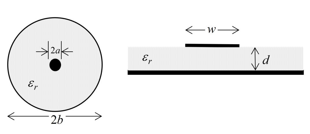
The most commonly used transmission lines in MRI are the coaxial and microstrip lines. Both are characterized by the spacing between the two conductors, the dimensions of one or both conductors, and the dielectric material surrounding the conductors. Both carry energy in the TEM mode. Formulas for the impedance of these transmission lines are readily available.
The major manufacturers have excellent websites which explain both basics and details of the parameters that you need to consider when purchasing transmission lines. In MRI, “50 ohm” cables are almost used exclusively. An important parameter is the attenuation per 100 ft., which is highly frequency dependent. A second is the power and/or voltage handling capability. A cable that may be fine for a receive coil, and may even handle the average power applied during a pulse sequence, may not be able to handle the applied peak voltage. As an example, consider two Belden cables, both of type RG58A/U. Belden part number 8219 lists a maximum operating voltage of 300 V RMS, while part number 8840 lists a maximum operating voltage of 1400 V RMS [23]. Note that the voltage on a transmission line can increase significantly if there is impedance mismatch. This is not only due to standing waves on the line, but because the transmit power may need to be increased significantly to account for the mismatch! Other factors include the percentage of shielding, which can range from 100% shielding, or even double shielding, down to relatively poor braided shields with 40% coverage that can leak significantly. Additionally, not all cables are non-magnetic, an obvious concern for in-bore applications.
Applications: transmission lines as devices
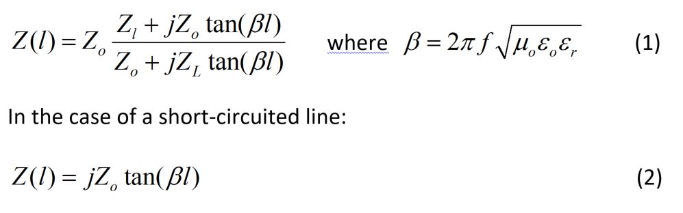
Transmission lines are commonly used to form various RF devices instead of or in combination standard circuit elements. Examples include transmit/receive switches, “baluns”, phase shifters for coil isolation and decoupling as well as for simple phase control in transmit arrays [24]. Simple transmission line networks can also be used to split or combine power equally between two or more (matched) ports, using a Wilkinson divider [25]. These can even be extended to match over dual bands [26] and even to force equal currents on multiple array elements regardless of loading or coupling [27, 28]. Of course, perhaps the most useful and general application of transmission lines is their ability to generate, or transform, impedances. Ignoring loss in the line, we can obtain any reactive value from a shorted or open-circuited transmission line. The input impedance Z(l) of a transmission line of characteristic impedance Zo, physical length l meters, terminated with an impedance ZL is given by Eq 1 in Fig. 2. β is the propagation constant for the transmission line.
An important aspect of transmission lines is the velocity factor, which accounts for the slower-than-free-space propagation in the line. For most coaxial transmission lines, the velocity factor, vf, is 0.66, meaning that the effective wavelength in a transmission line is 0.66 times the physical length of the transmission line. In the above equations this is taken into account through the propagation constant β. If the line is short-circuited at the end, this simplifies as also given in Fig. 2.
This behavior has been used for a variety of applications since the earliest days of NMR, ranging from transmission line tuned dual frequency coils [29] to diplexers for inserting or separating dual frequencies from a single transmission line [30] to the construction of matching networks for RF amplifiers [31]. Another important application that will be discussed is the use of transmission lines as “baluns” or “cable-traps” to prevent current on the outside of transmission lines [32, 33].
Smith charts and network analyzers
An important tool for understanding and analyzing the impedance transformation properties of transmission lines is the Smith chart [34]. This is a graphical tool that forms the basis of the display of most vector network analyzers, the basic tool of coil designers and RF engineering. A variety of programs are available that provide PC and smartphone based implementations of the Smith chart. These programs are very useful for impedance matching and transformation applications in particular.A few emerging applications
As magnet strengths increased, researchers recognized the potential to use dielectric materials to manipulate the fields inside the bore to optimize performance of RF coils (shimming) as well as how to use dielectric materials instead of copper as the RF coils themselves[9, 11, 35]. As mentioned above, at 7T the bore can actually act as a propagating waveguide (TE11 mode), enabling a variety of new and exciting potential approaches to MRI RF coils [36-39]. We might even see reconfigurable MRI antennas using wave guidance technology [40].
Finally, the emergence of metamaterials may open up dramatically new capabilities based on the ability to control and create negative relative permittivity (and permeability) [16, 41, 42]. Metamaterials are already finding application in MRI acting as transmission media to focus or carry RF fields to/from coils and as lenses for focusing RF field [16, 17], for example. Additionally metamaterials may overcome some of the narrowband properties of some transmission line devices, such as Wilkinson power dividers and baluns [43].
Conclusion
Guidance of RF signals is fundamental to MRI, from simply interconnecting two subsystems to designing matching networks, to tailoring RF fields inside the patient. In this talk an overview of conventional transmission lines, waveguides and resonators is provided, focusing on applications of conventional transmission lines in properly transferring signals to the RF coil and back.Acknowledgements
No acknowledgement found.References
[1] C. A. Balanis, Advanced engineering electromagnetics. Wiley New York, 1989.
[2] D. K. Cheng, "Fundamentals of engineering electromagnetics," 1993.
[3] H. P. Neff, Basic electromagnetic fields. HarperCollins Publishers, 1987.
[4] R. F. Lee, C. R. Westgate, R. G. Weiss, D. C. Newman, and P. A. Bottomley, "Planar strip array (PSA) for MRI," Magnetic Resonance in Medicine: An Official Journal of the International Society for Magnetic Resonance in Medicine, vol. 45, no. 4, pp. 673-683, 2001.
[5] J. T. Vaughan, H. P. Hetherington, J. O. Otu, J. W. Pan, and G. M. Pohost, "High frequency volume coils for clinical NMR imaging and spectroscopy," Magnetic Resonance in Medicine, vol. 32, no. 2, pp. 206-218, 1994.
[6] X. Zhang, K. Ugurbil, and W. Chen, "Microstrip RF surface coil design for extremely high‐field MRI and spectroscopy," Magnetic resonance in medicine, vol. 46, no. 3, pp. 443-450, 2001.
[7] M. V. Vaidya, C. M. Deniz, C. M. Collins, D. K. Sodickson, and R. Lattanzi, "Manipulating transmit and receive sensitivities of radiofrequency surface coils using shielded and unshielded high-permittivity materials," Magnetic Resonance Materials in Physics, Biology and Medicine, pp. 1-12, 2018.
[8] B. Zhang, D. K. Sodickson, and M. A. Cloos, "A high-impedance detector-array glove for magnetic resonance imaging of the hand," Nature Biomedical Engineering, vol. 2, no. 8, p. 570, 2018.
[9] T. P. O'reilly, T. Ruytenberg, and A. G. Webb, "Modular transmit/receive arrays using very‐high permittivity dielectric resonator antennas," Magnetic resonance in medicine, vol. 79, no. 3, pp. 1781-1788, 2018.
[10] K. Haines, N. Smith, and A. Webb, "New high dielectric constant materials for tailoring the distribution at high magnetic fields," Journal of Magnetic Resonance, vol. 203, no. 2, pp. 323-327, 2010.
[11] K. Haines, T. Neuberger, M. Lanagan, E. Semouchkina, and A. Webb, "High Q calcium titanate cylindrical dielectric resonators for magnetic resonance microimaging," Journal of Magnetic Resonance, vol. 200, no. 2, pp. 349-353, 2009.
[12] A. Kangarlu et al., "Dielectric resonance phenomena in ultra high field MRI," Journal of computer assisted tomography, vol. 23, no. 6, pp. 821-831, 1999.
[13] H. Wen, F. A. Jaffer, T. J. Denison, S. Duewell, A. S. Chesnick, and R. S. Balaban, "The evaluation of dielectric resonators containing H 2 O or D 2 O as RF coils for high-field MR imaging and spectroscopy," Journal of Magnetic Resonance, Series B, vol. 110, no. 2, pp. 117-123, 1996.
[14] D. Kajfez and P. Guillon, "Dielectric resonators," Norwood, MA, Artech House, Inc., 1986, 547 p. No individual items are abstracted in this volume., vol. 1, 1986.
[15] K. Koolstra, P. Börnert, W. Brink, and A. Webb, "Improved image quality and reduced power deposition in the spine at 3 T using extremely high permittivity materials," Magnetic resonance in medicine, vol. 79, no. 2, pp. 1192-1199, 2018.
[16] D. R. Smith, W. J. Padilla, D. C. Vier, S. C. Nemat-Nasser, and S. Schultz, "Composite Medium with Simultaneously Negative Permeability and Permittivity," Physical Review Letters, vol. 84, no. 18, pp. 4184-4187, 05/01/ 2000.
[17] M. J. Freire, L. Jelinek, R. Marques, and M. Lapine, "On the applications of μr=-1 metamaterial lenses for magnetic resonance imaging," Journal of Magnetic Resonance, vol. 203, no. 1, pp. 81-90, 2010.
[18] G. Scott and K. Yu, "Wireless transponders for RF coils: systems issues," in ISMRM 13th Annual Meeting, 2005, p. 330.
[19] J. Wei, Z. Liu, Z. Chai, J. Yuan, J. Lian, and G. X. Shen, "A realization of digital wireless transmission for MRI signals based on 802.11 b," Journal of Magnetic Resonance, vol. 186, no. 2, pp. 358-363, 2007.
[20] O. G. Memis, Y. Eryaman, O. Aytur, and E. Atalar, "Miniaturized fiber-optic transmission system for MRI signals," Magnetic Resonance in Medicine, vol. 59, no. 1, pp. 165-173, 2008.
[21] M. J. Riffe, M. D. Twieg, N. Gudino, C. J. Blumenthal, J. A. Heilman, and M. A. Griswold, "Identification and mitigation of interference sources present in SSB‐based wireless MRI receiver arrays," Magnetic Resonance in Medicine, vol. 70, no. 6, pp. 1775-1786, 2013.
[22] K. Aggarwal et al., "A Millimeter-Wave Digital Link for Wireless MRI," IEEE transactions on medical imaging, vol. 36, no. 2, pp. 574-583, 2017.
[23] (3/10/2019). RG Coaxial and Triaxial Reference Guide. Available: https://info.belden.com/hubfs/resources/technical/product-brochures-bulletins/rg-coaxial-and-triaxial-reference-guide-product-bulletin.pdf?hsLang=en
[24] G. Adriany et al., "Transmit and receive transmission line arrays for 7 Tesla parallel imaging," Magnetic Resonance in Medicine: An Official Journal of the International Society for Magnetic Resonance in Medicine, vol. 53, no. 2, pp. 434-445, 2005.
[25] D. M. Pozar, Microwave engineering. John Wiley & Sons, 2009.
[26] P. Myun-Joo and L. Byungje, "A Dual-Band Wilkinson Power Divider," Microwave and Wireless Components Letters, IEEE, vol. 18, no. 2, pp. 85-87, 2008.
[27] J. Cui, I. E. Dimitrov, S. Cheshkov, M. Gu, C. R. Malloy, and S. M. Wright, "An Adjustable-Length Dipole Using Forced-Current Excitation for 7T MR," IEEE Transactions on Biomedical Engineering, vol. 65, no. 10, pp. 2259-2266, 2018.
[28] J. Cui et al., "A switched-mode breast coil for 7 T MRI using forced-current excitation," IEEE Transactions on Biomedical Engineering, vol. 62, no. 7, pp. 1777-1783, 2015.
[29] V. R. Cross, R. K. Hester, and J. S. Waugh, "Single coil probe with transmission‐line tuning for nuclear magnetic double resonance," Review of Scientific Instruments, vol. 47, no. 12, pp. 1486-1488, 1976.
[30] P. Zanek, "A Low-Loss VHF/UHF Diplexer," QEX, pp. 47-51, Mar/Apr 2002.
[31] K. Feng, N. A. Hollingsworth, M. P. McDougall, and S. M. Wright, "A 64-channel transmitter for investigating parallel transmit MRI," Biomedical Engineering, IEEE Transactions on, vol. 59, no. 8, pp. 2152-2160, 2012.
[32] D. M. Peterson, B. L. Beck, G. R. Duensing, and J. R. Fitzsimmons, "Common mode signal rejection methods for MRI: reduction of cable shield currents for high static magnetic field systems," Concepts in Magnetic Resonance Part B: Magnetic Resonance Engineering, vol. 19, no. 1, pp. 1-8, 2003.
[33] D. Seeber, J. Jevtic, and A. Menon, "Floating shield current suppression trap," Concepts in Magnetic Resonance Part B: Magnetic Resonance Engineering, vol. 21, no. 1, pp. 26-31, 2004.
[34] P. H. Smith, "Transmission line calculator," Electronics, vol. 12, no. 1, pp. 29-31, 1939.
[35] A. Webb, "Visualization and characterization of pure and coupled modes in water-based dielectric resonators on a human 7T scanner," Journal of Magnetic Resonance, vol. 216, pp. 107-113, 2012.
[36] D. O. Brunner, N. De Zanche, J. Fröhlich, J. Paska, and K. P. Pruessmann, "Travelling-wave nuclear magnetic resonance," Nature, vol. 457, no. 7232, pp. 994-998, 2009.
[37] A. G. Webb, C. M. Collins, M. J. Versluis, H. E. Kan, and N. B. Smith, "MRI and localized proton spectroscopy in human leg muscle at 7 tesla using longitudinal traveling waves," Magnetic Resonance in Medicine, vol. 63, no. 2, pp. 297-302, 2010.
[38] D. O. Brunner, J. Paška, J. Froehlich, and K. P. Pruessmann, "Traveling-wave RF shimming and parallel MRI," Magnetic Resonance in Medicine, vol. 66, no. 1, pp. 290-300, 2011.
[39] Y. Pang, D. B. Vigneron, and X. Zhang, "Parallel traveling‐wave MRI: A feasibility study," Magnetic Resonance in Medicine, vol. 67, no. 4, pp. 965-978, 2012.
[40] H. Changzhou, S. Zhongxiang, and L. Jian, "High-Efficiency Sea-Water Monopole Antenna for Maritime Wireless Communications," Antennas and Propagation, IEEE Transactions on, vol. 62, no. 12, pp. 5968-5973, 2014.
[41] W. J. Padilla, D. N. Basov, and D. R. Smith, "Negative refractive index metamaterials," Materials Today, vol. 9, no. 7–8, pp. 28-35, 7// 2006.
[42] G. V. Eleftheriades, "EM transmission-line metamaterials," Materials Today, vol. 12, no. 3, pp. 30-41, 3// 2009.
[43] M. A. Antoniades and G. V. Eleftheriades, "A broadband Wilkinson balun using microstrip metamaterial lines," Antennas and Wireless Propagation Letters, IEEE, vol. 4, pp. 209-212, 2005.
Figures