4180
Concurrent scalp and intracranial electroencephalography recording in a human 1.5T MRI scanner: RF-induced heating assessment1Department of Clinical and Experimental Epilepsy, University College London, London, United Kingdom, 2Department of Clinical and Experimental Epilepsy, Epilepsy Society, Buckinghamshire, United Kingdom, 3Administration of Medical Physics, King Abdullah Medical City (KAMC), Makkah, Saudi Arabia, 4Lysholm Department of Neuroradiology, UCLH NHS Trust, London, United Kingdom, 5Department of Brain Repair and Rehabilitation, UCL Institute of Neurology, London, United Kingdom, 6Department of Experimental Epilepsy, National Hospital for Neurology and Neurosurgery, London, United Kingdom, 7Developmental Imaging and Biophysics Section, UCL Great Ormond Street Institute of Child Health, London, United Kingdom, 8Wellcome EPSRC Centre for Medical Engineering, King's College London, London, United Kingdom
Synopsis
The acquisition of electroencephalography (EEG) concurrently with functional magnetic resonance imaging (fMRI) requires careful consideration of the health hazards resulting from interactions between the scanner’s electromagnetic fields and EEG recording equipment. with excessive RF-induced heating near the electrodes being the main one. In view of performing concurrent scalp and intracranial EEG-MRI, we measured heating in the vicinity of electrodes placed within and on a phantom during high-SAR sequences in two conditions: with intracranial electrodes only, and following the addition of scalp electrodes. Temperature variations were well within the safety guidelines at all measurement locations in both conditions.
Introduction
Concurrent electroencephalography (EEG) and functional magnetic resonance imaging (EEG-fMRI) data acquisitions must be the subject of careful evaluation of potential health hazards due to interactions between the EEG system and MRI fields.1 At clinical field strengths, RF-induced heating of the body in the vicinity of the scalp EEG electrodes and leads has been found to be the most important safety hazard.2,3 Concurrent intracranial EEG-fMRI (icEEG-fMRI) is a more recent development, 4 made possible following tests that demonstrated that it can be performed with an acceptable level of additional risk, under specific controlled conditions.5,6 In view of our interest in performing concurrent scalp and icEEG recordings during fMRI for the study of epileptic activity in humans, we measured RF-induced heating in the vicinity of the electrodes.Methods
Two sets of temperature measurements were performed on a phantom: Experiment 1: with icEEG electrodes placed inside the phantom; Experiment 2: with the addition of scalp EEG electrodes.
Phantom: A new phantom was manufactured based on the ASTM standard, 7 consisting of a realistically shaped head and torso. The external surface of the head has disk-shaped indentations positioned following the 10-20 system. The head was filled with a gel made of water, 4% Agar (Sigma-Aldrich, Germany), 0.5% NaCl and 4 ml/l of Milton (preservative agent), 8 and the torso with 19 l of distilled water, 8 g/l of poly-acrylic acid, 0.7 g/l NaCl.7,9
For Experiment 1, five icEEG electrodes were used: two 8-contact (R: right temporal; LB: left temporal posterior) and one 6-contact depths (LA: left temporal anterior) lateral trajectories; one 6-contact strip (S; left parietal-frontal); and one 6x8-contact grid (G; right frontal) (Ad-Tech Medical, USA) following1,5.
For Experiment 2, six subdermal EEG electrodes (Ives EEG Solutions, USA) were placed on the exterior surface of the head phantom (with the icEEG electrodes left in place) by insertion into modelling clay in the indentations at EEG electrode positions: F3, F7, FP1, FP2, T3, and T5, chosen to maximise heating based on pilot data.
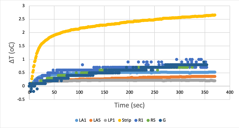
Temperature measurements: Experiment 1: 7 fibre-optic sensors (Neoptix, Canada) were placed at the following icEEG contacts: R #1 (R-1; near the tip) and #5 (R-5; 2cm from R-1 laterally). LA #1 (LA-1) and #5 (LA-5). LP #1 (LP-1), S #6 (S-6; near the tip), G #48 (G-48; posterior side of the grid). An 8th sensor was placed in the torso as a reference. For Experiment 2, five fibre-optic sensors (OpSens, Canada) were attached to scalp electrodes F3, F7, FP1, FP2, and T5.
RF exposure: A Siemens 1.5T Avanto (Siemens AG, Germany) was used with a transmit RF body coil. For Experiment 1 the phantom was exposed to a high-SAR fast spin echo (FSE) sequence (two repetitions; scanner-reported SAR: 2.9±0.1 W/kg head-average); for Experiment 2, in addition to the FSE sequences a low-SAR gradient-echo echo-planar (EPI) sequence was applied (SAR: 0.1±0.1 W/kg). The two experiments took place on different days with the phantom removed between the two sessions.
Results
Experiment 1: for the FSE sequences, the peak temperature change was +2.7°C at S-6 (Figure 1; the temperature differences between the two repetitions were below 0.1°C).
Experiment 2: following the addition of the scalp electrodes, the peak temperature change for the FSE sequences were +2.1°C at S-6; and +0.6°C at FP2 . For the EPI sequence, the values were <0.1 0C for all icEEG electrodes; and +0.7°C at T5.
Discussion and Conclusion
The observed peak temperature increases in the vicinity of the icEEG electrodes are in line with our previous observations without scalp electrodes5; and the addition of the subdermal scalp electrodes resulted in variations in the peak temperature increases at the icEEG electrodes within ±1°C for the high-SAR sequences. These results suggest that the addition of the scalp electrodes do not increase the risk significantly. For EPI, the peak temperature increases were ≤ +0.7°C, with the maximum heating at a scalp electrode location, and the heating at all intracranial electrodes ≤ ±0.1°C.
The use of subdermal scalp EEG electrodes in combination with icEEG electrodes for fMRI does not pose a higher risk than our previously demonstrated icEEG-fMRI protocol.10
Acknowledgements
This research was partly supported by National Institute for Health Research UCL Hospitals Biomedical Research Centre, United Kingdom.References
1. Carmichael DW, Thornton JS, Rodionov R, et al. Safety of localizing epilepsy monitoring intracranial electroencephalograph electrodes using MRI: radiofrequency-induced heating. J Magn Reson Imaging. 2008;28:1233–44.
2. Hawsawi HB, Carmichael DW, Lemieux L. Safety of Simultaneous Scalp or Intracranial EEG during MRI: A Review. Frontiers in Physics. 2017;42:52-76.
3. Vulliemoz S, Carmichael DW, Rosenkranz K, et al. Simultaneous intracranial EEG and fMRI of interictal epileptic discharges in humans. Neuroimage. 2011;54(1):182–190.
4. Vulliemoz S, Lemieux L, Daunizeau J, et al. The Combination of EEG Source Imaging and EEG-Correlated Functional MRI to Map Epileptic Networks. Epilepsia. 2010;51(4):491–505
5. Carmichael DW, Thornton JS, Rodionov R, et al. Feasibility of simultaneous intracranial EEG-fMRI in humans: A safety study. Neiroimage. 2010;49(1):379-390.
6. Ciumas C, Schaefers G, Bouvard S, et al. A phantom and animal study of temperature changes during fMRI with intracerebral depth electrodes. Epilepsy Res. 2013;108(1):57–65.
7. Park SM, Nyenhuis JA, Smith CD, et al. Gelled versus nongelled phantom material for measurement of MRI-induced temperature increases with bioimplants. IEEE Trans Magn. 2003;39(5):3367–71.
8. Yan WX, et al. Understanding gradient artefacts in simultaneous EEG/fMRI. Neuroimage. 2009;46(2):459-71.
9. ASTMF 2182-02a. Standard Test Method for Measurement of Radio Frequency Induced Heating Near Passive Implants during Magnetic Resonance Imaging. ASTM Committee F04 on Medical and Surgical Materials and Devices, Subcommittee F04.15 on Material Test Methods. West Conshohocken, PA: ASTM International;2007.
10. Carmichael DW, Vulliemoz S, Rodionov R, et al. Simultaneous intracranial EEG–fMRI in humans: Protocol considerations and data quality. Neuroimage. 2012;63(1):301-309.
Figures