1576
Self-decoupled coils for MRI receiver arrays based in an external resonator1Technical University of Denmark, Kgs. Lyngby, Denmark
Synopsis
A method of decoupling coils by the use of an external resonator has been developed. The method provides several advantages as a decoupling strategy which does not strongly depend on the input impedance of the amplifier, can use flexible wires and provide a low dependence of the coupling to the position of one coil relative to the other. The concept was initially developed for cryogenic coils due to its simple implementation but is presented to room temperature Copper-based receivers.
Introduction
An array composed by several coils can be a significantly complicated task to tune and match all the channels. If cryogenic arrays of coils are considered, this task is even more complicated since an easy tuning is not possible due to the mechanical constraints introduced by the low temperature of operation. The self-decoupled coil based in an external resonator method introduces a simple way of implementing receiver channels decoupling. The decoupling between receiver coils is achieved by the use of an external high Q factor resonant circuit which forces the excited loop current to flow through an external inductor instead the receiver loop coil.Methods
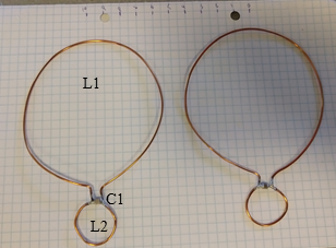
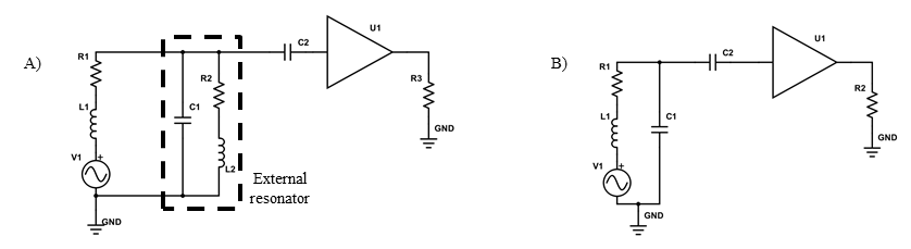
Two self-decoupled coils, each based on an external resonator (Figure 1 and Figure 2A), and two standard single loop resonating coils, composed by a loop in parallel with a tuning capacitor (Figure 2B), have been built to evaluate and compare their characteristics in terms of decoupling and SNR. The loop coils were built with 1 mm thick wire and 8 cm diameter. The tests were performed for each pair of coils of the same type and the distance between them has been changed while measuring the center frequency of the resonance of each coil. Two overlapped loop antennas with 2 cm diameter each were used to excite and measure the center frequency shift while decreasing the distance between the coils from 10 cm to an overlapped condition of 2 cm. The self-decoupled coil with external resonator method is based on a concept of removing the tank circuit from the loop coil to avoid the resonator current to flow through it. This is achieved by adding a coil with a inductance L2 in parallel to the loop coil inductance L1, as shown in the equivalent schematic of Figure 2, where L1 is the loop coil and L2 is the external resonator inductor and L2<<L1. During the period that the resonator energy is stored as a magnetic field, it is stored in the lower inductance circuit and not in the higher inductance circuit due to the lower impedance of the L2 path. Properly choosing L1 and L2 values allows the current excited in the receiver loop coil to run through the inductor placed on the external resonator, L2, instead of through the magnetic field loop coil, L1, which minimizes the coupling between neighbour channels. Circuit simulations were performed to confirm the measured results and the response of the receiver as function of the loop inductance to a fixed resonator inductance of 40 nH with 2 cm diameter and tuning capacitor of 680 pF. An electromagnetic simulation (CST, Darmstad, Germany) has also been performed to crosscheck the absolute H-field behaviour at the proposed configuration of coils.Results and discussion
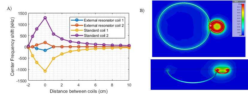
The decoupling of the proposed method is demonstrated
by measuring the center frequency shift as function of the distance between 2
coils. The results of these
measurements are shown in Figure 3. The external
resonator coil has a frequency shift of 2 kHz at 1 cm distance from the
neighbour coil while the standard resonating coil, has a center frequency shift
of 560 kHz. SNR measurements
have also been performed at the same test conditions for both coils and it was
possible to verify an SNR difference between the self-decoupled coils to a
resonant single element coil of approximately 50%.
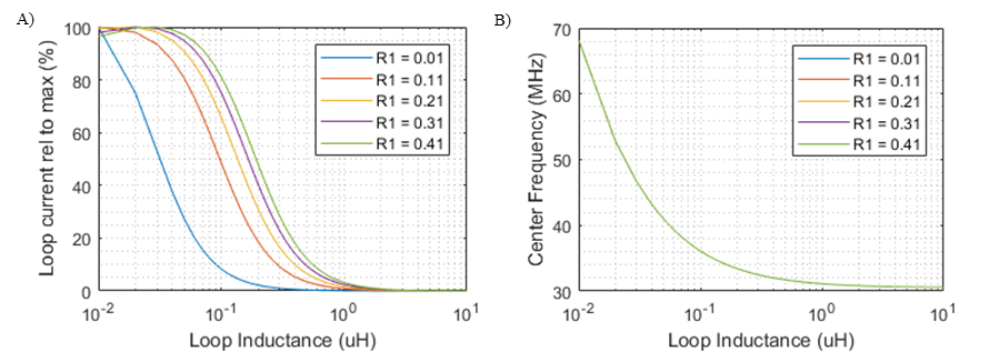
The percentage of current flowing through the voltage loop
coil as function of its inductance is shown in Figure 4.
For the mentioned resonator, a loop coil with approximately 300 nH gives a loop
coil current which is approximately 10% of the current flowing through a
standard resonating coil. For the analysed case, where the external resonator
inductance, L2, is around 40 nH, loop inductances higher than 300 nH results in
a current flowing through the inductor L1 which is 10% of the current of a
single loop resonant coil. The electromagnetic simulations shows that the
absolute H-field stored in the in loop coil, L1, has approximately 10% of the H-field
intensity that is stored in the coil L2.Conclusion
The
self-decoupled coil based on the external resonator was demonstrated to
significantly decrease the coupling between neighbour coils due to the low
current flowing through the main loop. Flexible coils have been tested, and
they can be easily used as loop elements as well as easily adjusted to the
sample shape to allow a better coil fitting. The method applied to cryogenic
coils improves its performance due to the higher Q factor of the external
resonator and to the reduction of the receiver loop coil resistance.Acknowledgements
This work was supported in part by the Danish National Reseach Foundation.References
1. P. B. Roemer, W. A. Edelstein, C. E. Hayes, S. P. Souza, O. M. Mueller. The NMR Phased Array. Magnetic Resonance in Medicine, 1990; 16 (192-225)
2. Martin Suefke, et. al. External high-quality-factor resonator tunes up nuclear magnetic resonance. Nature Physics, 2015; 11
Figures