1463
Analysis of B0 Eddy Current in Superconducting MRI System Involving Main Coil Circuit1GE Global Research, Niskayuna, NY, United States
Synopsis
The B0 eddy current, which shifts the temporal B0 and is harmful to MR Image quality, hasn’t been analyzed in detail before. In this work, we provide a FEM-circuit co-simulation method for this problem and the result clearly shows that main superconducting coil plays an important role in shaping the B0 EC time constant and thus to include them in model is necessary for making accurate prediction.
Introduction
When gradient coils are pulsed in a MRI scanner, temporal and spatially dependent eddy currents(EC) are inevitable induced in the cryostat vessels of the magnet. The EC in turn generates a magnetic field, that adds to the desired gradient field, thus inducing image distortion artifacts[1]. During the past decades, not only hardware and software algorithms have been invented to reduce this issue [1,2], but also analytical and numerical methods have been applied to characterize the ECs. However, analyses usually focused on the gradient-type or odd-harmonics EC (and field) along the corresponding axial [3-7]. The B0 EC [1], which shifts the temporal B0, is different from the previously mentioned EC. Although the B0 EC is also harmful to MR imaging and needs to be eliminated or be compensated, the causing mechanism hasn’t been analyzed in detail. Since the intrinsic characteristic of the B0 EC implies it might be the result of coupling to both main coils and the cryostat, to involve the main superconducting coil is needed. Ideally, careful design of magnet and gradient coils could possibily result in no B0 EC, but due to the limitation of mechanical tolerance, B0 EC could be always in the system. In this work, we provide a FEM-Circuit co-simulation method to capture the B0 EC due to the asymmetry introduced by manufacturing error. We will focus on the EC by the z-gradient coils since they couple to the main coil most.
Methods
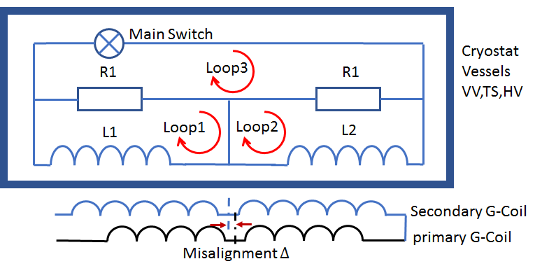
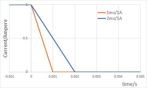
In Fig.1 the schematic diagram shows a simplified MRI system, consisting of the main superconducting coil circuit with two sub coils, the cryostat (i.e. vacuum vessel, thermal shield and helium vessel) and the gradient coil. The gradient coil set (only z-gradient here) includes the primary turns and secondary turns. Although the z coil set is of a symmetric design, we introduce a misalignment $$$\Delta$$$ in z direction between primary and secondary turns to mimic the manufacturing error during the assembly process. Assuming the source current in the gradient coil is $$$\vec{I_0}=a\vec{J_0}$$$ , where $$$a$$$ is cross-section area of the gradient coil conductor. Vector potential $$$\vec{A}$$$ satisfies $$\nabla\times\frac{1}{\mu}(\nabla\times\vec{A})=\vec{J_0}-\sigma\frac{\partial{\vec{A}}}{\partial{t}}\;\;\;\;\;\;\;\;\;\;\;\;\;\;\;\;\;\;\;\;\;\;\;\;\;\;\;\;\;\;\;\;\;\;\;\;\;\;\;\;\;\;\;\;\;\;\;\;\;\;\;\;\;\;\;\;\;\;\;\;\;\;\;\;\;\;\;\;\;\;\;\;\;\;\;\;\;\;\;\;\;\;\;\;\;\;\;\;\;\;\;\;\;\;\;\;\;\;\;\;(1)$$ from Maxwell Equations. For the main coils, since all the loops need to satisfy Kirchhoff Voltage Law, $$\sum_{j=1}^{2}M_{ji}\frac{\partial{I_i}}{\partial{t}}+R_i(I_i-I_3)=V^{ind}_i, i=1,2\text{ for Loop1, 2 and } \sum_{i=1}^{2}R_i(I_i-I_3)=0\text{ for Loop3}\;\;\;\;\;\;\;\;\;\;\;\;\;\;(2)$$ where $$$V^{ind}_i=-\int{\frac{\partial{\vec{A}}}{\partial{t}}}\cdot d\vec{l}$$$ is the induced voltage from Eqn.(1) and $$$M_{ji}$$$ and $$$R_i$$$ are mutual inductors and effective quench protection resistors of the main loops, respectively. In simulation, A ramp down waveform is used as the gradient coil driven current (Fig.2). The coupled simulation was conducted in COMSOL software [8].Results and Discussions
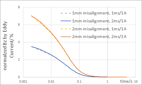
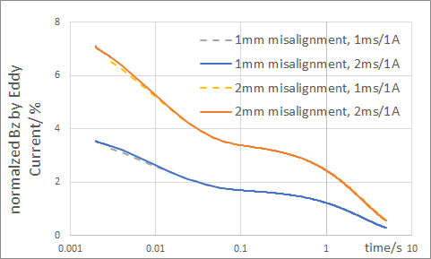
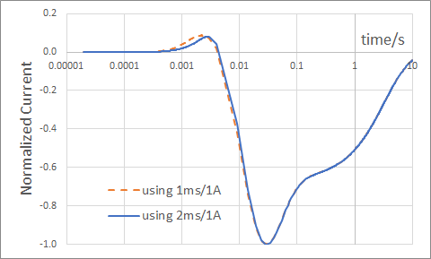
We simulated two scenarios for an experimental head z coil in a 3T head only system design[9]. The main coil was not involved in one scenario but was involved in the second. For each scenario, the $$$\Delta$$$ could be 1mm or 2mm. Meanwhile, 1ms/1A and 2ms/1A ramp down drive currents were used in the simulation. Since the EC responds to the $$$\frac{\partial{I_0}}{\partial{t}}$$$, we can expect the same results from the drive currents of different slopes. We measured the Bz field at ISO center by the EC and normalized to the gradient initial Bz field at z=1cm and summarized in Fig.3a and Fig.3b. From the figures, we can clearly see that due to the loss of symmetry, the gradient coil can generate a net B0 magnetic field by coupling to the main coils as well as the cryostat. When the main coils are involved, long time constant EC (Fig.4) is induced because of the relative big inductor-resistor ratio of the main loops, and that explains the reason the long time constant Bz from the EC could be observed in the real system. Without involving the main coil circuit in analysis, this long time constant EC could not exist since the material resistivity and geometry of the cryostat only support EC with time constant less than 100ms in this system.Conclusions
In this work, a FEM-Circuit co-simulation method is purposed to analyze B0 EC behavior of a 3T head only system due to the misalignment of the primary and the secondary turns of the z gradient coil set. The result clearly shows that main superconducting coil circuit plays an important role in shaping the B0 EC time constant and thus to include them in model is necessary for making accurate predictions. This analysis can be used to guide the assembly error control during manufacturing and image quality estimations. Further analysis could be about to extend this method to analyze B0 EC by transverse gradient coils.Acknowledgements
The work was supported in part by NIH R01EB010065 and U01EB02445.References
[1] William M. Spees, et al., “Quantification and compensation of eddy-current-induced magnetic-field gradients”, JMR, Vol212,2011:116-123
[2] Peter Roemer, John Hickey, Self-Shielded Gradient Coils For Nuclear Magnetic Resonance Imaging, US4737716
[3] T.Takahashi, “Numerical analysis of eddy current problems involving z gradient coils in Superconducting MRI magnets ”, IEEE Trans. Mag. Vol26(2), 1990:893-896
[4] Eugene. Badea, Ovidiu Craiu, “Eddy Current Effects in MRI Superconducting Magnets”, IEEE Trans. Mag. Vol33(2), 1997:1330-1333
[5] Feng Liu, Stuart Crozier, “An FDTD Model for Calculation of Gradient-Induced Eddy Currents in MRI System”, IEEE Trans. Applied Superconductivity. Vol14(3),2004:1983-1989
[6] Hector Sanchez Lopez, etl al, "Eddy current simulation in thick cylinders of finite length induced by coils of arbitrary geometry", JMR, vol207, 2010: 251-261.
[7] Hector Sanchez Lopez, et al., "Multilayer integral method for simulation of eddy currents in thin volumes of arbitrary geometry produced by MRI gradient coils", MRM, vol71, 2014:1912-1922.
[8]: COMSOL Multiphysics®. www.comsol.com. COMSOL AB, Stockholm, Sweden.
[9] Lee SK, et al, "Peripheral nerve stimulation characteristics of an asymmetric head-only gradient coil compatible with a high-channel-count receiver array", MRM, Vol76(6)2016:1939-1950
Figures