RF Transmit: Power Delivery, Decoupling & Duty Cycle
Natalia Gudino1
1National Institutes of Health, United States
Synopsis
This talk will cover different RF engineering methods used in the design and implementation of transmit systems currently available in clinical MRI settings and research sites.
Target audience
Those interested in learning about engineering concepts behind the design and implementation of MRI RF transmit systems.Objective
This presentation will focus on the following concepts emphasized for MRI applications:
- RF power requirements
- RF amplification and power transfer methods
- Power monitoring
- Quadrature versus linear transmit (TX) coils
- TX array and decoupling
- Non-conventional transmit hardware
- Applications
Introduction
The conventional RF transmit chain used in most MRI systems is shown in Figure 1. Power is transmitted from the RF power amplifier (RFPA) to the coil terminals through a long coaxial connection with 50 Ω characteristic impedance (Z0). Despite the direct relation between B1 transmit field and the current circulating the coil, most TX coils are controlled by voltage (similar to traditional radio communication systems). Thus, maximum power transfer to the coil is possible through an impedance matching network, built with LC elements or transmission line segments. This network connects directly to the coil terminals or through a multiple of λ/2 coaxial segment that keeps the matched impedance condition. The RFPA is usually a pulsed power voltage-mode quasi-linear amplifier with heatsink and water cooling, to dissipate the heat that results from the relatively low power efficiency amplification (< 60%). Typically, a volume type excitation requires tens of kW of pulsed power from the amplifier. Power requirements increase as we move to higher magnetic fields, not only because higher energy is necessary to resonate the spins ($$$\propto$$$B02), but also because cable losses increase with frequency. With the advance of high and ultra-high field MRI and the shift from quadrature volume excitation to multi-channel transmission, there is a trend to move away from this conventional chain as we will discuss in the presentation.Quadrature volume transmission
In most MRI setups, RF power is delivered to the sample by a volume transmitter while the MR signal is received through a RX array (Figure 1). Power is transferred to a single volume coil (e.g. a birdcage transmitter) through a Q-hybrid (operating as 2-way 90° power splitter), which generates two quadrature voltages to drive two ports located at a 90° azimuthal angle. Each of these voltages is maximized at the ports through a 50 Ω matching network and can be monitored through a directional coupler. A volume transmitter generates a circularly polarized (CP) magnetic field rotating at the excitation frequency (Larmor frequency). The performance of this transmitter decreases with field strength. At 1.5 T, the excitation wavelength is still shorter than the dimensions of the sample (near field regime), thus a CP field generates a very uniform transverse magnetization profile across a large field of view resulting in clinically valuable contrast for head and body imaging. Degraded performance of the volume excitation can be observed in imaging of the body at 3 T. To improve this, there are 3 T clinical systems that include a body coil transmitter with 2 ports independently controlled to shim the field in a selected ROI. At higher fields B1 homogeneity can be severely compromised and higher number of channels are necessary for correction.Multi-channel transmission
A multiple-channel transmitter, consists of an array of coils (e.g. surface coils), each generating a linearly polarized field that can be independently controlled (parallel transmit system) to generate different excitation modes (e.g. including a CP or gradient mode). This flexibility can be used to shim the B1 field at high and ultra-high field. In an ideal multi-channel transmit setup, total transmit power is given by the sum of power delivered per element (e.g. coil, stripline or dipole antenna). Therefore, the most common approach to drive a multi-channel TX array is to scale down the power and replicate the conventional TX chain (Figure 2). This is a straight forward approach that relies on the same TX hardware concepts broadly used in MRI. However, this setup is inherently coupled due to the multiple coaxial cables, networks and coil elements. Elements of the array can be decoupled by capacitive, inductive or geometric (element overlap or separation) methods. A well decoupled (< -15 dB isolation between channels) 50 Ω matched TX array allows for independent and power-efficient control per channel. However, with higher number of channels, greater the complexity of tuning, matching and decoupling adjustments necessary to have optimal pTx operation. Thus, pTx systems built from the conventional TX chain are usually limited to small number of channels. There are active efforts to develop high density TX arrays that rely on the design of new RF amplifiers [1-7], RF signal monitoring and control [9-12].Discussion
Correcting for B1 homogeneity at high field and improving implant safety at lower field are the main “propellers” for the development of parallel transmit systems. Multi-channel transmitters, built with the conventional TX chain, require complex tuning of the multiple impedance and decoupling networks. During my presentation, I will review methods that allow automatic adjustments to improve TX performance while reducing calibration time [13-16]. In addition, drastic modifications to the TX chain that attempt to eliminate, instead of compensate, some of the limitations in a pTx implementation will be presented. For example, transmit efficiency and control can be improved by replacing the linear or quasi-linear amplifiers by switch-mode amplifiers (e.g. class-E, class-D) [2,4,5]. A more direct control of the B1 field per channel can be achieved through a current source excitation, instead of the traditional voltage source. Simplification of the coil array by eliminating decoupling networks can be achieved by active decoupling methods such as feedback [10,11] or amplifier decoupling [1,5].Acknowledgements
No acknowledgement found.References
- Kurpad KN, Wright SM, Boskamp EB. RF current element design for independent control of current amplitude and phase in transmit phased arrays. Concepts Magn Reson Part B: Magn Reson Eng 2006; 29B:75–83.
- Heilman JA, Riffe MJ, Heid O, Griswold MA. High Power, High Efficiency On-Coil Current Mode Amplifier for Parallel Transmission Arrays. In Proceedings of the 15th Annual Meeting ISMRM, Berlin, Germany, 2007. Abstract 171.
- Chu X, Yang X, Liu Y, Sabate J, Zhu Y. Ultra-low output impedance RF power amplifier for parallel excitation. Magn Reson Med 2009;61: 952–961.
- Raab FH, Poppe MC, Myer DP. High-efficiency RF power-amplifier module for magnetic-resonance imaging. In Proceedings of the 19th Annual Meeting of ISMRM, Montreal, Canada, 2011. Abstract 1850.
- Gudino N, Heilman JA, Riffe MJ, Heid O, Vester M, Griswold MA. On-coil multiple channel transmit system based on class-D amplification and pre-amplification with current amplitude feedback. Magn Reson Med 2013;70:276–289.
- Gudino N, Duan Q, de Zwart JA, Murphy-Boesch J, Dodd SJ, Merkle H, van Gelderen P, Duyn JH. Optically controlled switch-mode current- source amplifiers for on-coil implementation in high-field parallel transmission. Magn Reson Med 2016;76:340–349.
- Twieg M, Griswold MA. High efficiency radiofrequency power amplifier module for parallel transmit arrays at 3 Tesla. Magn Reson Med 2017;78:1589–1598.
- Lee W, Boskamp E, Grist T, Kurpad K. Radiofrequency current source (RFCS) drive and decoupling technique for parallel transmit arrays using a high-power metal oxide semiconductor field-effect transistor (MOSFET). Magn Reson Med 2009;62:218–228.
- Hoult DI, Kolansky G, Kripiakevich D, King SB. The NMR multitransmit phased array: a Cartesian feedback approach. J Magn Reson 2004;171:64–70.
- Scott GC, Stang P, Kerr A, Pauly J. General Signal Vector Decoupling for Transmit Arrays. In Proceedings of the 16th Annual Meeting ISMRM, Toronto, Canada, 2008. Abstract 146.
- Stang PP, Kerr A, Pauly JM, and Scott GC, “An extensible transmit array system using vector modulation and measurement,” In Proceedings of the 16th Annual Meeting ISMRM, Toronto, Canada Canada, 2008, Abstract 145.
- Gudino N, de Zwart JA, Duan Q, Dodd SJ, Murphy-Boesch J, van Gelderen P, Duyn JH. Optically controlled on-coil amplifier with RF monitoring feedback.Magn Reson Med. 2018 May;79(5):2833-2841.
- Snyder C, DelaBarre L, Hess A, Rodgers C, Robson M, Vaughan T. A Separated Transmit-only, Receive-only Array for Body Imaging at 7T with Automated Tuning and Matching Capabilities. In Proceedings of the 21st Annual Meeting ISMRM, Salt Lake City, USA, 2013. Abstract 131.
- Mahmood Z , Guérin B, Adalsteinsson E, Wald LL, Daniel L. An Automated Framework to Decouple pTx Arrays with Many Channels. In Proceedings of the 21st Annual Meeting ISMRM, Salt Lake City, USA, 2013. Abstract 2722.
- Katsikatsos G, Pruessmann KP Closed-loop control for transmit array matching. In Proceedings of the 21st Annual Meeting ISMRM, Salt Lake City, USA, 2013. Abstract 2742.
- Keith GA, Rodgers CT, Hess AT, Snyder CJ, Vaughan JT, Robson MD. Automated tuning of an eight-channel cardiac transceive array at 7 tesla using piezoelectric actuators. Magn. Reson. Med. 2015 Jun;73(6):2390-7.
Figures
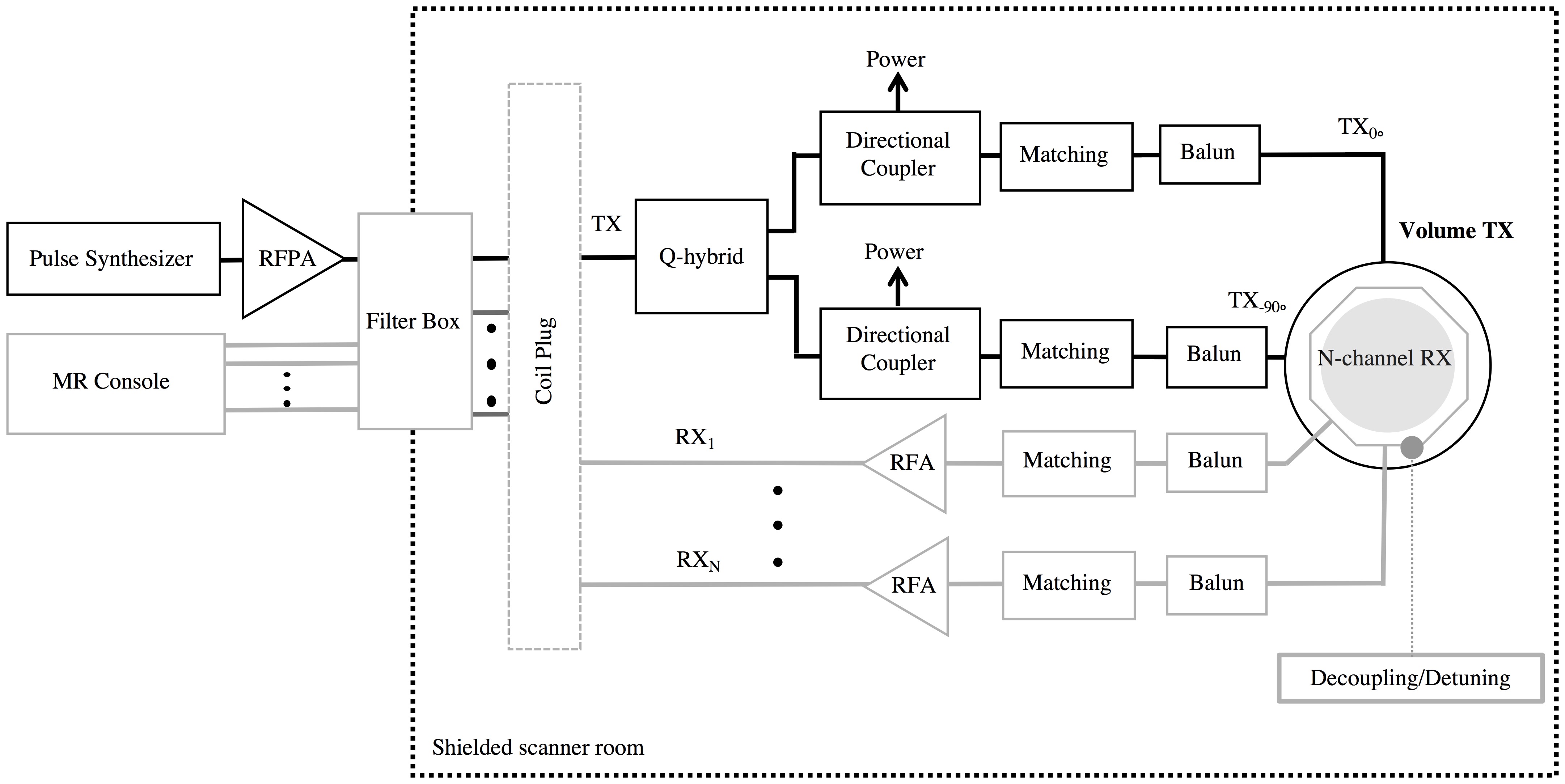
Figure 1: Conventional RF
setup. RF power is delivered to the sample through a quadrature volume
transmitter and MR signal is received through a RX array.
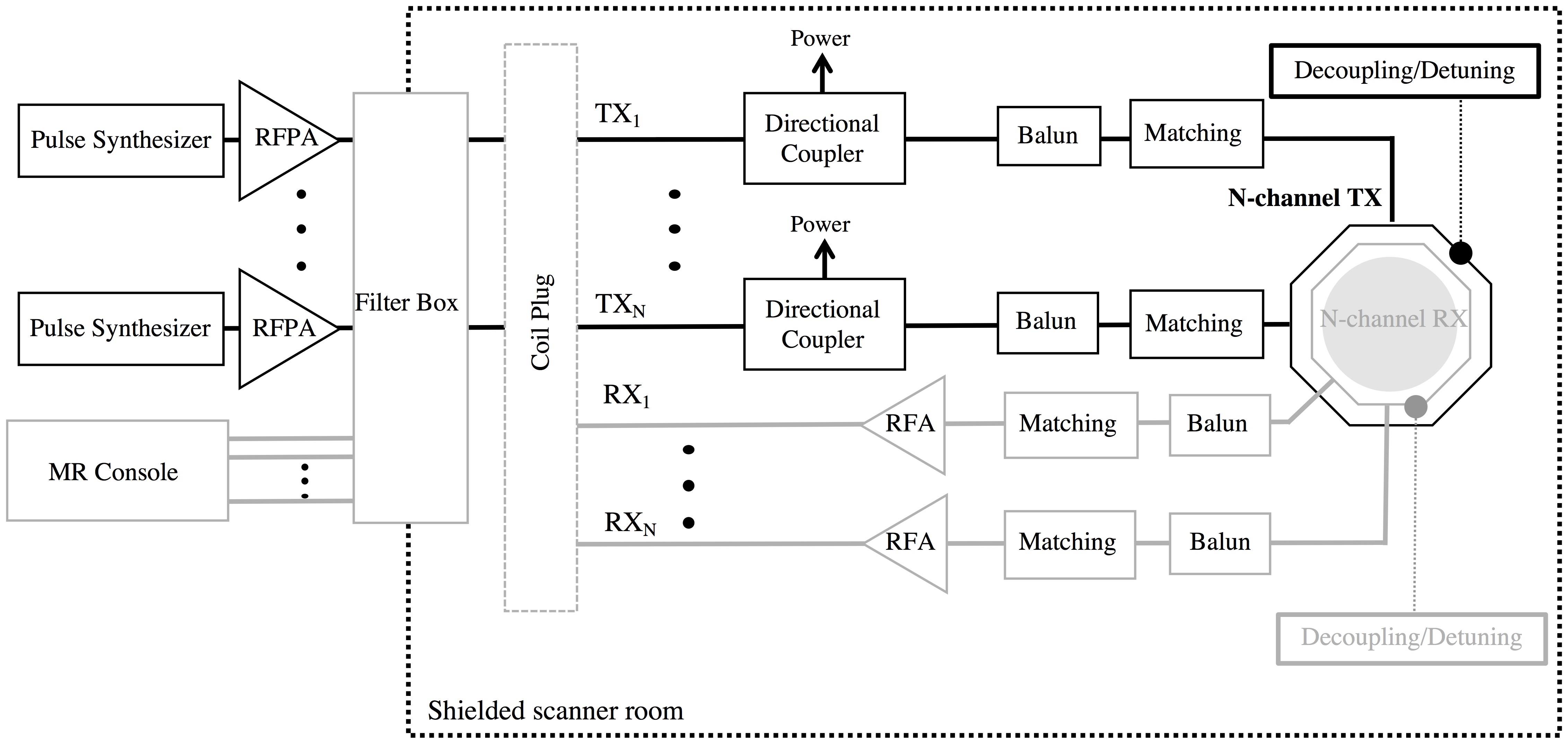
Figure 2:
Multi-channel TX setup based on conventional RF chain.