MR Imaging of Therapeutic Ultrasound
Chrit Moonen1
1University Medical Center Utrecht, Netherlands
Synopsis
High Intensity Focused Ultrasound (HIFU), similar to External Beam Radiotherapy (EBRT), can be guided by imaging to plan, provide real-time guidance, and evaluate the therapeutic efficacy. MRI has major advantages for guidance because of its superior anatomic detail, and for HIFU for its thermal mapping. Here, we will pay particular attention how MRI can be used to describe and correct displacement of the target area.
Introduction
Two treatment options for local tumor control have the potential to achieve complete non-invasiveness: treatment by high intensity focused ultrasound (HIFU 1,2) and external beam radiotherapy (EBRT 3,4). MRI has major advantages for guidance because of its superior anatomic detail, and for HIFU for its thermal mapping (see Figures 1 and 2). MR thermometry has been reviewed previously. In this presentation, we will address challenges presented by motion.Tumor motion
While HIFU and EBRT have the advantage of being completely non-invasive, their application in a clinical setting can become challenging due to displacements of the cancer relative to the therapeutic beam (5, 6). Depending on the nature of the displacement, the treated tissue may periodically, partially or permanently move-out of the beam-path. Spontaneous motion is particularly problematic for HIFU and EBRT therapies due to its fast and infrequent nature. Long-term motion often stems from digestive activity and/or metabolic processes. Such displacements manifest as temporal drifts, becoming significant over time intervals of several minutes (20). Finally, respiratory motion induces displacements with a frequency of 0.2 - 0.3 Hz (7,8). Fig. 2 showcases an example of liver displacements under the effect of both respiratory and long term motion.Motion prevention or reduction in HIFU and EBRT
Several methods and techniques that can be used to either prevent or reduce the extent of tumor displacements during HIFU and EBRT. Patient spontaneous motion, for example, can be prevented by body fixation via (custom-made) casts, molds and/or masks (9). A wide-spread solution for respiratory-related motion is provided by breath-hold techniques (7). However, both breath-holding and induced shallow breathing imply discomfort to the patient, often unfeasible in practice.Motion estimation methods
In order to estimate patient positioning inaccuracies, skin markings are typically made during treatment planning (10, 11). The coordinates/location of these markings are then recorded. The integration of on-board medical imaging systems into HIFU and EBRT provides alternative motion estimation solutions. The basic principle of image-based motion tracking relies on comparing two images, where one of the images provides a positional reference (12). The result is usually a set of displacements. Compared to CT and MR, US-guidance is a relatively cheap alternative, while provides high-framerate imaging. This is well suited for tracking fast motion events such as respiration. Due to its high versatility for both anatomical and functional imaging, MRI is generally the guidance method of choice for HIFU therapies. A simple approach is given by using so-called navigator echoes (13, 14), fast 1D MR acquisitions, with a field-of-view typically encompassing high-contrast organ boundaries. Naturally, navigator echoes usually do not allow estimation of complex deformations, however, they have proved to be particularly useful for gating energy deliveries for both HIFU and EBRT (15-17). For more complex deformations of abdominal organs high-framerate 2D MR-imaging is coupled with real-time motion estimation algorithms. In this sense, Denis de Senneville et al proposed an atlas-based real-time motion estimation, in which dynamic 2D MR imaging is performed during pre-treatment, with each image stored in an atlas together with a pixel-by-pixel motion field (18). The motion field is determined by means of the Horn & Schunck optical flow algorithm. During energy delivery, rapid MR imaging is performed and an inter-correlation coefficient is computed between each acquired image and the pre-acquired atlas. The motion field associated to the image in the atlas which provides the highest correlation coefficient is then selected. Other ongoing studies for real-time 3D MR-based respiratory motion estimation, follow an approach similar to the one proposed by Denis de Senneville et al: a 2D MR image acquired during energy deliveries is correlated to an atlas of 3D volumes pre-acquired during a learning phase (19). See Figues 3-5 for examples.Motion compensation techniques in HIFU and EBRT
Once the extent of the tumor motion is estimated, measures can be taken in order to compensate for its effects on therapy. A standard approach is to incorporate uncertainties related to the extent of the displacements into the therapeutic margins (20). Such an approach ensures that the therapeutic endpoint is achieved. Aside from including the potential displacements in the treatment margins, several other solutions have been proposed. Compensating for patient positioning errors, in particular, is relatively straight-forward. Once these are estimated, based on skin and/or implanted markers, the therapeutic table is adjusted such that the position of the markers at the time of treatment is roughly the same as during planning. Compensating for spontaneous, long-term and/or respiratory motion, on the other hand, is typically addressed via two major approaches: gating or beam-steering. Gating implies the activation of the therapeutic beam only when the targeted organ/pathology is in a pre-defined rage of positions called gating window. This implicitly increases the total treatment delivery time which is problematic for HIFU in organs such as the liver and kidneys, where the high perfusion affects can cause strong heat dissipation effects. Thus, continuous operation of the therapeutic beam would be preferable over gating. By steering the beam with respect to the estimated motion, localized energy deposition can be achieved, without reducing duty cycle. Other studies employed phased HIFU transducers to dynamically re-adjusting the focus position. For EBRT modulation of the radiation beam with respect to the estimated motion is achieved by using a multi-leaf collimator (MLC, 21). It was demonstrated that motion compensation during EBRT is achievable, by morphing the aperture of the MLC according to the estimated tumor displacements (22, 23). The delay between the actual displacement of the tumor and the corresponding adjustments made to the therapeutic beam can be problematic(6, 7, 24). This delay incorporates the image acquisition time (in case image guidance is used), the latency of the motion estimation algorithm, the duration of the data transfer through the system and the inertia of the beam steering mechanism. Most studies which propose beam steering solutions for HIFU and/or EBRT also include a motion prediction algorithm, in order to compensate for the effects of such latencies (25-27).Acknowledgements
The HIFU team at the University Medical Center Utrecht is gratefully acknowledged, in particular Cornel Zachiu whose thesis served as the basis of this presentation.References
1) J. E. Kennedy. Nat Rev Cancer, 5(4):321 – 327, 2005. 2) Y.-S. Kim, H. Rhim, M. J. Choi, H. K. Lim, and D. Choi. Korean J Radiol, 9(4):291 – 302, 2008. 3) S. Webb. Physica Medica, 17:207 – 215, 2001. 4) M. K. Bucci, A. Bevan, and M. Roach 3rd. CA Cancer J Clin, 55(2):117 – 134, 2005. 5) S. S. Korreman. Phys Med Biol, 57(23):R161 – R191, 2012. 6) B. Denis de Senneville, C. Moonen, and M. Ries. In Escoffre, J. - M. and Bouakaz, A., editor, Therapeutic Ultrasound, pages 43 – 63. Springer, 2015. 7) P. J. Keall, G. S. Mageras, J. M. Balter, R. S. Emery, K. M. Forster, S. B. Jiang, J. M. Kapatoes, D. A. Low, M. J. Murphy, B. R. Murray, C. R. Ramsey. Med. Phys, 33(10):3874 – 3900, 2006. 8) A. Muller, L. Petrusca, V. Auboiroux, P. J. Valette, R. Salomir, and F. Cotton. Cardiovasc Intevent Radiol, 36(6):1464 – 1476, 2013. 9) L. J. Verhey. Semin Radiat Oncol, 5(2):100 – 114, 1995. 10) K. Wurstbauer, F. Sedlmayer, and H. D. Kogelnik. Int J Radiat Oncol Biol Phys, 50(1):179 – 181, 2001. 11) S. Rathod, A. Munshi, and J. Agarwal.. South Asian J Cancer, 1(1):27 – 29, 2012. 12) J. B. Maintz and M. A. Viergever. Md Image Anal, 2(1):1 – 36, 1998. 13) J. de Zwart, F. C. Vimeux, J. Palussi`ere, R. Salomir, B. Quesson, C. Delalande, and C. T. Moonen. Magn Reson Med, 45)(1):128 – 137, 2001. 14) M. O. K¨ohler, B. Denis de Senneville, B. Quesson, C. T. Moonen, and M. Ries. Magn Reson Med, 66(1):102 – 111, 2011. 15) S. P. Crijns, B. W. Raaymakers, and J. J. Lagendijk. Phys Med Biol, 57(23):7863 – 7872, 2012. 16) J. W. Wijlemans, M. de Greef, G. Schubert, L. W. Bartels, C. T. Moonen, M. A. van den Bosch, and Ries M. Invest Radiol, 50(1):24 – 31, 2015. 17) V. Auboiroux, L. Petrusca, M. Viallon, A. Muller, S. Terraz, R. Breguet, X. Montet, C. D. Becker, and R. Salomir. Biomed Res Intl, 2014:421726, 2014. 18) B. Denis de Senneville, C. Mougenot, and C. T. Moonen. Magn Reson Med, 57(2):319 – 330, 2007. 19) B. Stemkens, R. Tijssen, B. Denis de Senneville, J. J. Lagendijk, and C. A. van den Berg. Phys Med Biol, 61(14):5335 – 5355, 2016. 20) M. van Herk. Semin Radiat Oncol, 14(1):52 – 64, 2004. 21) P. J. Keall, V. R. Kini, S. S. Vedam, and R. Mohan. Phys Med Biol, 46(1):1 – 10, 2001. 22) A. Sawant, R. Venkat, V. Srivastava, D. Carlson, S. Povzner, H. Cattell, and P. Keall. Med Phys, 35(5):2050 – 2056, 2008. 23) P. Keall, E. Colvill, R. O’Brien, J. A. Ng, P. R. Poulsen, T. Eade, A. Kneebone, and J. T. Booth. Med Phys, 41(2):020702, 2014. 24) P. R. Poulsen, B. Cho, A. Sawant, D. Ruan, and P. J. Keall. Med Phys, 37(9):4998 – 5005, 2010. 25) D. Ruan. Phys Med Biol, 55(5):1311 – 1326, 2010. 26) A. Krauss, S. Nill, and U. Oelfke. Phys Med Biol, 56(16):5303 – 5317, 2011. 27) P. Arnold, F. Preiswerk, B. Fasel, R. Salomir, K. Scheffler, and P. C. Cattin. Med Image Comput Comput Assist Interv, 14(Pt 2):623 – 630, 2011.Figures
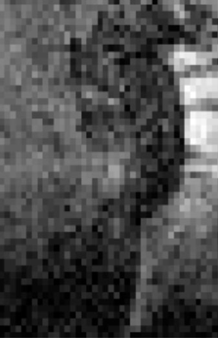
Magnitude
of a gradient-recalled echo MR image acquired on a kidney during a HIFU ablation.
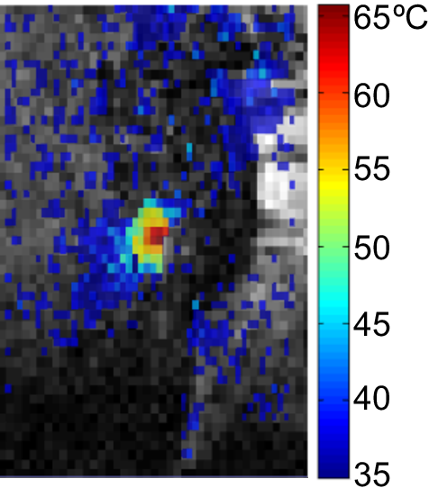
The
corresponding thermal map (based on the proton resonance frequency shift of
tissue water) overlaid on the magnitude image in Figure 1.
An
example of liver displacements under the effect of respiratory and long term
motion.
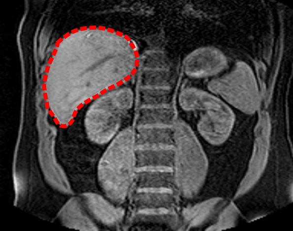
Coronal
slice of a 3D MR image acquired on the abdomen of a healthy volunteer. The
liver is indicated by the red dashed contour.
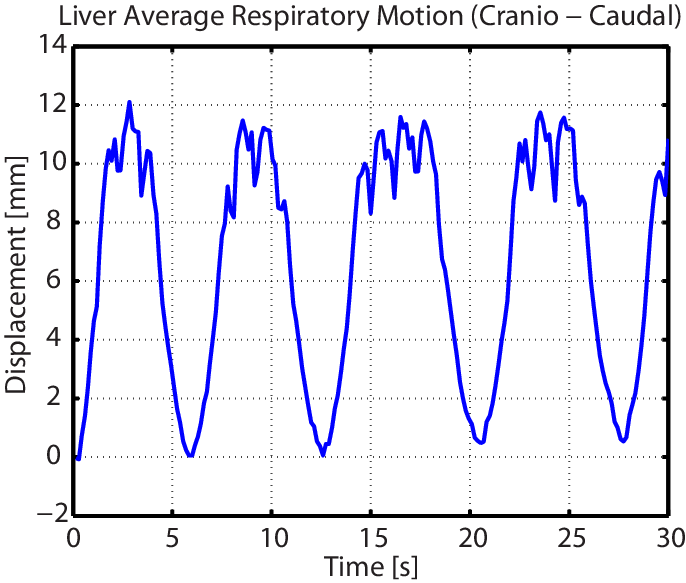
Average
displacement of the liver (see Figure 3) in the cranio-caudal direction under
the effect of respiration.
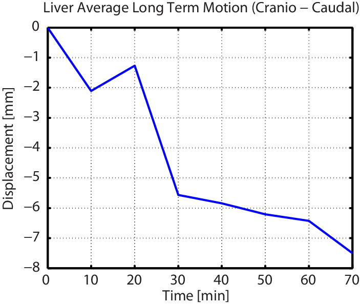
Long-term
motion of the liver (see Figure 3) in the cranio-caudal direction.