Multi-Tuned Coils
1University Medical Center Utrecht, Netherlands
Synopsis
Ever wanted to build your own multi-tuned RF coil to enable metabolic imaging? This 30 minute session will start from scratch and ends with you capable to make the most advanced multi-tuned, transmit and receive coil array (in theory)...
Introduction
The Radiofrequent (RF) coil is one of the most important components in magnetic resonance. Its function is to manipulate the spins and detect their response. When the RF field of the coil (B1) is placed perpendicular to the main magnetic field (B0) and an oscillating magnetic field is created, spins are perturbed once the frequency of oscillation meets the Larmor frequency of the spins and when the rotation of the B1 field has a component that meets the rotation of the spins (B1+). By driving the RF coil with an RF amplifier, a B1+ field strength can be obtained that manipulate the spins sufficiently within an order of ms. However, the RF power required to generate the B1+ field will be absorbed by the RF coil and the tissue, which can lead to heating and may impose a safety concern that needs to be addressed carefully. When using the RF coil as a receiver, the oscillating net magnetic flux originating from the relaxing spins can be captured by the coil, which will result in an induced voltage that after amplification (using a preamplifier) can be detected and digitized. The sensitivity of the detection is directly related to the efficiency of the receiver coil and can therefore be optimized for any point of interest in space taking the boundaries of the sample into consideration. For larger regions of interest, sensitivity may be compromised in case of reception with a single coil or remain optimized when an array of receiver coils is used. In fact, as the array of coils may each have a unique spatial dependent sensitivity, their sensitivity profiles can be used to spatially encode the MR signal (SENSE), hence accelerating MR imaging. Since most RF coils are tuned for narrow band operation optimized for the Larmor frequency of protons, MR imaging and spectroscopy using spins from other nuclei, like 13C, 31P, 19F and others, can not be obtained with these RF coils. Considering the substantially different Larmor frequencies of these nuclear spins, while still enabling detection of 1H spins, different RF coil concepts are required. In this course, the basic steps will be presented for the design, construction and use of multi-tuned RF coils. The course will start with a brief theory in RF electronics followed by practical dual-tuned coil designs used for transmission and/or reception.Theory
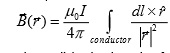
Coil Efficiency The number one determinant in MR technology for optimal SNR is the RF coil that can be used to transmit RF for excitation and receives the MR signals. The SNR obtained with a receiver coil is proportional to the efficiency of the coil, which according to the principle of reciprocity [1] is equal to the efficiency of the coil as a transmitter. The efficiency of an RF coil is expressed as the magnetic field strength per unit of applied RF power as a quadratic relation (in T/√W). Circularly polarized fields and B1 field strength A magnetic field can be generated by an electrical current flow (I) through a conductor. Per unit current the strength and orientation of this field in the object that is measured can be approximated using the law of Biot-Savart (as long as the wavelength of the RF is larger than the size of the object, which is the case for mouse MR at field strength up to 20T [2], or human head MR up to 3T, or other nuclear MR at even higher fields): (formula in Fig 3)
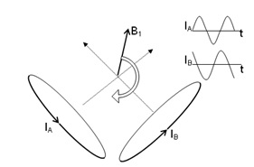
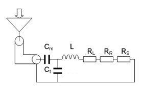
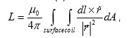
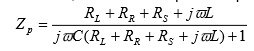
, (1) where dl is the length of a part of the conductor, r is a vector pointing from the location of the conductor part to the location of the point in space from where the magnetic field strength is calculated, and μ0 is the magnetic permeability constant in vacuum (i.e. 4π x 10-7). In order to create a B1 field that rotates around the main magnetic field, a second conductor is required that generates an equal but orthogonal field with respect to the first conductor. When the electrical current through the orthogonal conductors oscillates with a frequency equal to the Larmor precession, with a 90º-phase difference, a rotating magnetic field (circularly polarized) is generated (Fig. 1). Compared to a single coil setup (linearly polarized field) this quadrature setup requires twice as less power for the same B1, hence improves SNR by 41% (√2). Tuning and Matching An optimal transformation of RF power from an RF amplifier into current through the conductors is obtained when the conjugated impedance (Z*) of the amplifier matches the transformed impedance (Z) of the conductor. The impedance of the conductor can be split into a real part that absorbs power (i.e. resistance R) and an imaginary part that can temporarily store and release power (i.e. admittance X). The resistance of the conductor that generates a magnetic field in a sample consists of three parts: one part (RL) that depends on the conductivity, length and cross-section of the conductor, including skin effects at high operating frequencies; one part (RR) is related to radiation losses, which relates to the operating frequency, size of the conductor and the electro magnetic properties of the surroundings; and finally a part (RS) that is related to the relative power absorbed due to eddy-currents and electric fields in conductive tissue. The admittance of the conductor is linearly proportional to the frequency of operation and the inductance (L) of the conductor, where L can be calculated as (see equation in Figure 4): , (2) where the conductor encloses a loop (coil) with a surface area A. In total, the impedance of the conductor is: Z=RL+RR+RS+jωL, where j=√-1. This impedance needs to be transformed to the impedance of the RF amplifier (typically 50Ω), which can be realized by a simple capacitive network. A parallel capacitor (Ct) can be connected to both ends of the conductor, which creates a parallel impedance Zp (see equation in Fig 5). (3) In case the real part of Zp is tuned to 50Ω (using the appropriate value for Ct), the imaginary part of Zp can be eliminated by adding a capacitor (Cm) in series with Zp with admittance equal to the negative admittance of Zp. In this case the impedance of the inductor parallel to Ct and in series with Cm matches the 50Ω of the RF amplifier (Fig. 2).
Double-tuning
Using the schematic as indicated above, the RF coil will be operational for one frequency only. The simplest way to provide an RF coil setup that can be operational at two frequencies is to add another RF coil tuned at the other frequency. These two RF coils should be aligned such that their fields are either completely orthogonal, or include a certain overlap between the elements that provide a zero net flux linkage. However, such setup limits the number of coil elements to two or three [3], preventing the use of quadrature coil alignments for both frequencies. An alternative would be to apply blocking circuitries in the coil elements. These are additional parallel resonant circuits, tuned to the frequency that needs to be blocked. The consequently high impedance of this resonant circuit will stop currents at the corresponding frequency while hardly effecting the currents of the desired frequency. This way, multiple single tuned coil setups can be merged into a multi nuclear coil setup [4,5]. A single coil element can also be designed as a double-tuned element. In this way, all capacitor as indicated in figure 2 need to be replaced by circuitry consisting of a parallel resonant circuit (inductor parallel to capacitor) in series with another capacitor [6,7]. The resonance frequency of the parallel resonant circuit will be between the two frequencies of interest. As a consequence, this impedance acts as a capacitance for the highest frequency, while an inductance at the lowest frequency. The additional series capacitance will tune the original inductance including the additional inductance to the lowest frequency of interest. To minimize the losses by adding such double-tuned circuitry, the inductance of the parallel circuit should be substantially smaller than the inductance of the coil, and its Q value should be high (i.e. not close to conductive tissue) [8]. Coil testing Although the formulas presented here may be used to understand the electronics of RF coils, the fact that most values can actually be measured makes optimization of the quality of the coil construction a powerful method. The B1 field can be measured using the MR system by adjusting the integral of an RF pulse up to a 90 or 180 degree pulse for the region of interest. For instance if a 50μs rectangular RF pulse leads to a 90 degree pulse of the 1H spins, than the B1 field would be (4x50μsx42.6MHz/T)-1. The power (P) that was needed to create this RF pulse is given by the MR system either directly in Watts, or as an attenuation factor (att) in dB (P = Pmaxx10att/10, where Pmax is the maximum peak power of the RF amplifier) or in Voltage (U) (P = U2/50). The values for the capacitors can be determined by adjusting the resonance frequency of the coil setup, which can be determined by measuring the reflected RF power as a function of frequency (reflection curve). Generally this can be done with the MR system during a coil-tuning procedure, using a network-analyzer or with a low cost handheld RF sweeper. Matching to the system impedance is obtained when the measured reflected RF power is zero at the Larmor frequency (f0). The self inductance (L) of the coil can be approximated by L = 1/Ct(2πf0)2. The values for the resistances in the coil can be indirectly determined by measuring the quality (Q) factor of the coil. In a well matched condition, the Q value is inverse related to the bandwidth of the reflection curve (Q = 2f0/Δf-3dB), where Δf-3dB is the difference between the two frequencies for which half of the RF power is reflected. Assuming RR to be negligible, RL+RS can be determined as RL+RS = 2πf0L/Qloaded, where Qloaded is the determined Q factor of the coil loaded with the sample in place. If the range of capacitances is sufficient to also tune and match the coil in an unloaded situation, RL can be determined as RL= 2πf0L/Qunloaded. Under the assumption that different types of coils are all matched to 50Ω, the detected noise (N) from this 50Ω point no longer depends on the type of RF coil as it is related to: , (5) where Δf is the receiver bandwidth. This means that the SNR obtainable by the coil is linearly related to the efficiency of the coil measured at this 50Ω point, enabling comparisons of different coil types with respect to SNR.Conclusion
RF coils are key components in determining the quality of magnetic resonance. With a selection of scalable geometries of the coil that consider sample boundaries, any coil can be tuned and matched to the impedance of the MR systems at its operating frequencies. Using either blocking circuits in multiple single tuned RF coils or multi-tuned RF coils, multi nuclear MR setups can be designed at highest sensitivity and lowest RF power deposition as well. Consequently, dedicated RF coil setups can maximize the performance of MRI.Acknowledgements
No acknowledgement found.References
1. Hoult DI, Richards RE. Signal-to-noise ratio of nuclear magnetic-resonance experiment. J. Magn. Reson. 1976;24(1):71-85
2. Doty FD, Entzminger G, Kulkarni J, Pamarthy K and Staab JP. Radio frequency coil technology for small-animal MRI. NMR Biomed. 2007; 20: 304–325
3. Adriany G, Gruetter R. A half-volume coil for efficient proton decoupling in humans at 4 tesla. J Magn Reson. 1997 Mar;125(1):178-84.
4. Klomp DW, Renema WK, van der Graaf M, de Galan BE, Kentgens AP, Heerschap A. Sensitivity-enhanced 13C MR spectroscopy of the human brain at 3 Tesla. Magn Reson Med. 2006 Feb;55(2):271-8.
5. Klomp DW, van de Bank BL, Raaijmakers A, Korteweg MA, Possanzini C, Boer VO, van de Berg CA, van de Bosch MA, Luijten PR. (31) P MRSI and (1) H MRS at 7 T: initial results in human breast cancer. NMR Biomed. 2011 Dec;24(10):1337-42.
6. Brown R, Lakshmanan K, Madelin G, Parasoglou P. A nested phosphorus and proton coil array for brain magnetic resonance imaging and spectroscopy. Neuroimage. 2016 Jan 1;124(Pt A):602-611.
7. van der Velden TA, Italiaander M, van der Kemp WJ, Raaijmakers AJ, Schmitz AM, Luijten PR, Boer VO, Klomp DW.Radiofrequency configuration to facilitate bilateral breast (31) P MR spectroscopic imaging and high-resolution MRI at 7 Tesla. Magn Reson Med. 2015 Dec;74(6):1803-10
8. Fitzsimmons JR, Brooker HR, Beck B. A Comparison of double-tuned surface coils. Magn. Reson. Med. 1989; 10: 302–309.
Figures